CAMSHAFT REMOVAL

-
REMOVE TIMING CHAIN COVER SUB-ASSEMBLY
-
SET NO. 1 CYLINDER TO TDC/COMPRESSION
-
Temporarily install the crankshaft pulley bolt.
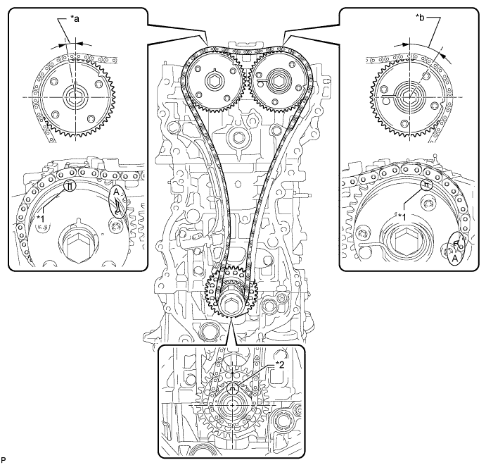
Text in Illustration *1 Timing Mark *2 Key *a Approximately 7° *b Approximately 32° Tech Tips
"A" is not a timing mark.
-
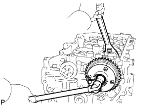
Rotate the crankshaft clockwise so that the timing marks on the crankshaft timing gear and camshaft timing gears are as shown in the illustration.
Tech Tips
If the timing marks do not align, rotate the crankshaft clockwise again and align the timing marks.
-
Remove the crankshaft pulley bolt.
-
-
REMOVE TIMING CHAIN GUIDE
-
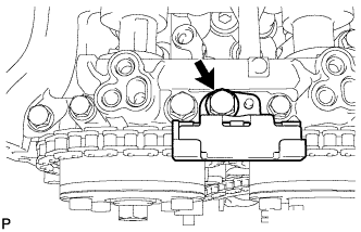
Remove the bolt and timing chain guide.
-
-
REMOVE NO. 1 CHAIN TENSIONER ASSEMBLY
-
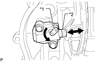
Text in Illustration *1 Stopper Plate *2 Plunger Allow the plunger to extend slightly, and then rotate the stopper plate counterclockwise to release the lock. Once the lock is released, push the plunger into the tensioner.
-
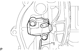
Text in Illustration *1 Pin Move the stopper plate clockwise to set the lock, and insert a pin into the stopper plate hole.
-
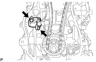
Remove the 2 bolts, chain tensioner and gasket.
-
-
REMOVE CHAIN TENSIONER SLIPPER
-
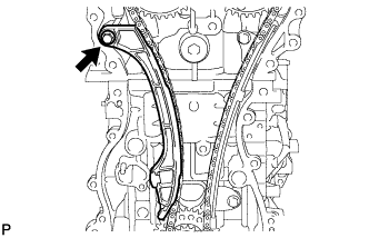
Remove the bolt and chain tensioner slipper.
-
-
REMOVE CHAIN SUB-ASSEMBLY
-
Remove the chain sub-assembly.
-
-
REMOVE NO. 1 CHAIN VIBRATION DAMPER
-
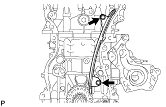
Remove the 2 bolts and No.1 chain vibration damper.
-
-
REMOVE CAMSHAFT TIMING GEAR ASSEMBLY
-
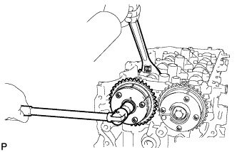
Hold the hexagonal portion of the camshaft with a wrench and remove the bolt and camshaft timing gear.
Note
-
Be careful not to damage the cylinder head or spark plug tube with the wrench.
-
Do not disassemble the camshaft timing gear.
-
-
-
REMOVE CAMSHAFT TIMING EXHAUST GEAR ASSEMBLY
-
Hold the hexagonal portion of the camshaft with a wrench and remove the bolt and camshaft timing exhaust gear.
Note
-
Be careful not to damage the cylinder head or spark plug tube with the wrench.
-
Do not disassemble the camshaft timing exhaust gear.
-
-
-
REMOVE CAMSHAFT HOUSING SUB-ASSEMBLY
-
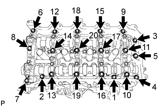
Uniformly loosen and remove the 20 bearing cap bolts in the sequence shown in the illustration.
-
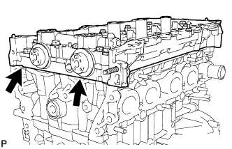
Remove the camshaft housing by prying between the cylinder head and camshaft housing with a screwdriver.
Tech Tips
Tape the screwdriver tip before use.
Note
Be careful not to damage the contact surfaces of the cylinder head and camshaft housing.
-
-
REMOVE CAMSHAFT BEARING CAP
-
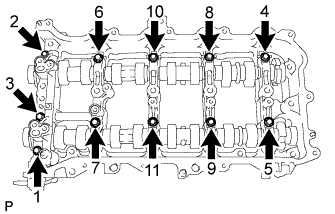
Remove the 11 bearing cap bolts in the sequence shown in the illustration.
-
Remove the 5 bearing caps.
Tech Tips
Arrange the removed parts in the correct order.
-
-
REMOVE OIL CONTROL VALVE FILTER
-
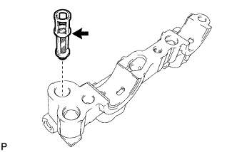
Remove the oil control valve filter from the No. 1 camshaft bearing cap.
-
-
REMOVE NO. 1 CAMSHAFT BEARING
-
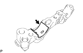
Remove the No. 1 camshaft bearing.
-
-
REMOVE CAMSHAFT
-
Remove the No. 1 and No. 2 camshafts.
-
-
REMOVE NO. 2 CAMSHAFT BEARING
-
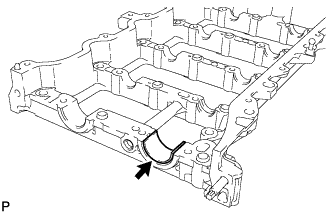
Remove the No. 2 camshaft bearing.
-
-
REMOVE NO. 1 VALVE ROCKER ARM SUB-ASSEMBLY
-
Remove the 16 valve rocker arms from the cylinder head.
Tech Tips
Arrange the removed parts in the correct order.
-
-
REMOVE VALVE LASH ADJUSTER ASSEMBLY
-
Remove the 16 valve lash adjusters from the cylinder head.
Tech Tips
Arrange the removed parts in the correct order.
-