SFI SYSTEM Starter Signal Circuit
DESCRIPTION
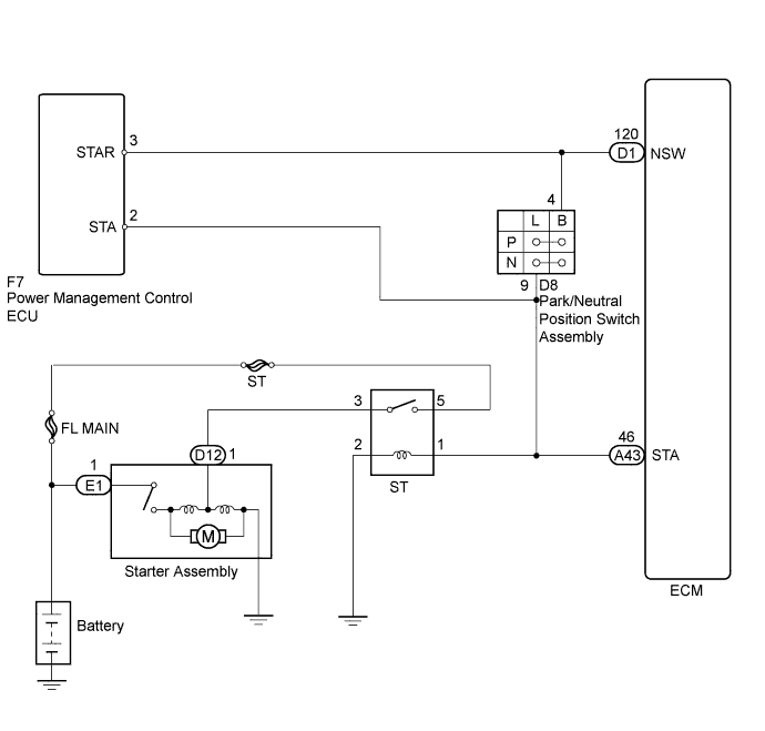
While the engine is being cranked, current flows from terminal STAR of the power management control ECU to the park/neutral position switch assembly and also flows to terminal STA of the ECM and power management control ECU (STA signal).
WIRING DIAGRAM
INSPECTION PROCEDURE
Note
Inspect the fuses for circuits related to this system before performing the following inspection procedure.
Tech Tips
This diagnosis procedure is based on the premise that the engine can crank normally. If the engine cannot crank normally, proceed to the Problem Symptoms Table Click here.
PROCEDURE
-
READ VALUE USING INTELLIGENT TESTER (STARTER SIGNAL)
-
Connect the intelligent tester to the DLC3.
-
Turn the engine switch on (IG).
-
Turn the tester on.
-
Enter the following menus: Powertrain / Engine / Data List / All Data / Starter Signal.
-
Read the value displayed on the tester when the engine switch is turned on (IG) and the engine is started.
OK Switch Condition Tester Display Engine switch on (IG) Close (Starter signal OFF) Engine started Open (Starter signal ON)
NG 
CHECK ST RELAY (POWER SOURCE) Click here
OK 
PROCEED TO NEXT SUSPECTED AREA SHOWN IN PROBLEM SYMPTOMS TABLE Click here
-
-
CHECK ST RELAY (POWER SOURCE)
-
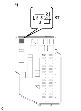
Text in Illustration *1 Engine Room Relay Block and Junction Block Assembly Remove the ST relay from the engine room relay block and junction block assembly.
-
Measure the voltage according to the value(s) in the table below.
Standard Voltage Tester Connection Condition Specified Condition 1 (ST relay terminal) - Body ground Engine cranking position 11 to 14 V Tech Tips
The engine will not crank because the relay is not installed.
-
Reinstall the ST relay.
NG
CHECK HARNESS AND CONNECTOR (ST RELAY - PARK/NEUTRAL POSITION SWITCH ASSEMBLY) Click here
OK
REPAIR OR REPLACE HARNESS OR CONNECTOR (ECM - PARK/NEUTRAL POSITION SWITCH ASSEMBLY)
-
-
CHECK HARNESS AND CONNECTOR (ST RELAY - PARK/NEUTRAL POSITION SWITCH ASSEMBLY)
-
Remove the ST relay from the engine room relay block and junction block assembly.
-
Disconnect the park/neutral position switch assembly connector.
-
Measure the resistance according to the value(s) in the table below.
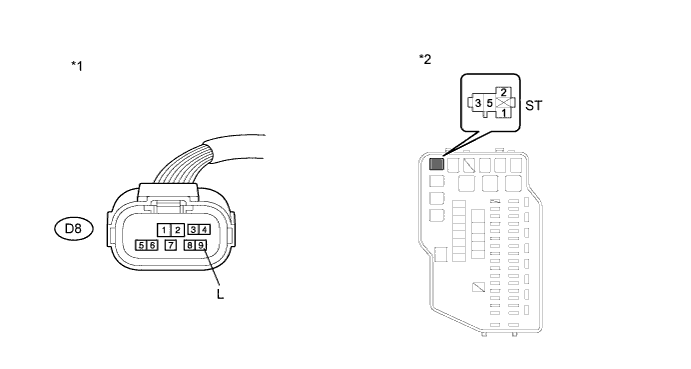
Standard Resistance (Check for Open) Tester Connection Condition Specified Condition 1 (ST relay terminal) - D8-9 (L) Always Below 1 Ω Standard Resistance (Check for Short) Tester Connection Condition Specified Condition 1 (ST relay terminal) or D8-9 (L) - Body ground Always 10 kΩ or higher Text in Illustration *1 Front view of wire harness connector
(to Park/Neutral Position Switch Assembly)
*2 Engine Room Relay Block and Junction Block Assembly -
Reinstall the ST relay.
-
Reconnect the park/neutral position switch assembly connector.
NG 
REPAIR OR REPLACE HARNESS OR CONNECTOR (ST RELAY - PARK/NEUTRAL POSITION SWITCH ASSEMBLY)
OK 
-
-
INSPECT PARK/NEUTRAL POSITION SWITCH ASSEMBLY
-
Inspect the park/neutral position switch assembly Click here.
NG
REPLACE PARK/NEUTRAL POSITION SWITCH ASSEMBLY Click here
OK
-
-
CHECK HARNESS AND CONNECTOR (POWER MANAGEMENT CONTROL ECU - ECM)
-
Disconnect the power management control ECU connector.
-
Disconnect the ECM connector.
-
Disconnect the park/neutral position switch assembly connector.
-
Measure the resistance according to the value(s) in the table below.
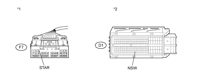
Standard Resistance (Check for Open) Tester Connection Condition Specified Condition F7-3 (STAR) - D1-120 (NSW) Always Below 1 Ω Standard Resistance (Check for Short) Tester Connection Condition Specified Condition F7-3 (STAR) or D1-120 (NSW) - Body ground Always 10 kΩ or higher Text in Illustration *1 Front view of wire harness connector
(to Power Management Control ECU)
*2 Front view of wire harness connector
(to ECM)
-
Reconnect the power management control ECU connector.
-
Reconnect the ECM connector.
-
Reconnect the park/neutral position switch assembly connector.
NG
REPAIR OR REPLACE HARNESS OR CONNECTOR (POWER MANAGEMENT CONTROL ECU - ECM)
OK
-
-
CHECK HARNESS AND CONNECTOR (PARK/NEUTRAL POSITION SWITCH - POWER MANAGEMENT CONTROL ECU)
-
Disconnect the park/neutral position switch assembly connector.
-
Disconnect the power management control ECU connector.
-
Remove the ST relay from the engine room relay block and junction block assembly.
-
Measure the resistance according to the value(s) in the table below.
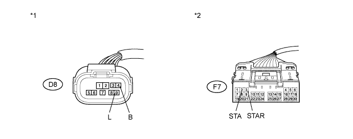
Standard Resistance (Check for Open) Tester Connection Condition Specified Condition D8-4 (B) - F7-3 (STAR) Always Below 1 Ω D8-9 (L) - F7-2 (STA) Always Below 1 Ω Standard Resistance (Check for Short) Tester Connection Condition Specified Condition D8-4 (B) or F7-3 (STAR) - Body ground Always 10 kΩ or higher D8-9 (L) or F7-2 (STA) - Body ground Always 10 kΩ or higher Text in Illustration *1 Front view of wire harness connector
(to Park/Neutral Position Switch Assembly)
*2 Front view of wire harness connector
(to Power Management Control ECU)
-
Reconnect the power management control ECU connector.
-
Reconnect the park/neutral position switch assembly connector.
-
Reinstall the ST relay.
NG
REPAIR OR REPLACE HARNESS OR CONNECTOR (PARK/NEUTRAL POSITION SWITCH - POWER MANAGEMENT CONTROL ECU)
OK
-
-
CHECK HARNESS AND CONNECTOR (PARK/NEUTRAL POSITION SWITCH ASSEMBLY - ECM)
-
Disconnect the ECM connector.
-
Disconnect the park/neutral position switch assembly connector.
-
Remove the ST relay from the engine room relay block and junction block assembly.
-
Measure the resistance according to the value(s) in the table below.
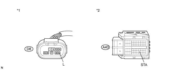
Standard Resistance (Check for Short) Tester Connection Condition Specified Condition D8-9 (L) or A43-46 (STA) - Body ground Always 10 kΩ or higher Text in Illustration *1 Front view of wire harness connector
(to Park/Neutral Position Switch Assembly)
*2 Front view of wire harness connector
(to ECM)
-
Reconnect the ECM connector.
-
Reconnect the park/neutral position switch assembly connector.
-
Reinstall the ST relay.
NG
REPAIR OR REPLACE HARNESS OR CONNECTOR (PARK/NEUTRAL POSITION SWITCH ASSEMBLY - ECM)
OK
GO TO ENTRY AND START SYSTEM Click here
-