SFI SYSTEM, Diagnostic DTC:P0011, P0012, P0021, P0022

| DTC Code | DTC Name |
|---|---|
| P0011 | Camshaft Position "A" - Timing Over-Advanced or System Performance (Bank 1) |
| P0012 | Camshaft Position "A" - Timing Over-Retarded (Bank 1) |
| P0021 | Camshaft Position "A" - Timing Over-Advanced or System Performance (Bank 2) |
| P0022 | Camshaft Position "A" - Timing Over-Retarded (Bank 2) |
DESCRIPTION
Refer to DTC P0010 Click here.
| DTC No. | DTC Detection Condition | Trouble Area |
|---|---|---|
| P0011 P0021 |
Valve timing is not adjusted in valve timing advance range (1 trip detection logic) |
|
| P0012 P0022 |
Valve timing is not adjusted in valve timing retard range (2 trip detection logic) |
|
WIRING DIAGRAM
Refer to DTC P0010 Click here.
INSPECTION PROCEDURE
Tech Tips
| Abnormal Bank | Timing Over Advanced (Valve timing is out of specified range) |
Timing Over Retarded (Valve timing is out of specified range) |
|---|---|---|
| Bank 1 | P0011 | P0012 |
| Bank 2 | P0021 | P0022 |
-
If DTC P0011 or P0012 is displayed, check the intake camshaft circuit for the right bank VVT system (bank 1).
-
Bank 1 refers to the bank that includes cylinder No. 1.
-
If DTC P0021 or P0022 is displayed, check the intake camshaft circuit for the left bank VVT system (bank 2).
-
Bank 2 refers to the bank that does not include cylinder No. 1.
-
DTC P0011, P0012, P0021 or P0022 may be set when foreign objects in the engine oil are caught in some parts of the system. The DTC will remain set even if the system returns to normal after a short time. These foreign objects may then be captured by the oil filter.
-
Read freeze frame data using the intelligent tester. The ECM records vehicle and driving condition information as freeze frame data the moment a DTC is stored. When troubleshooting, freeze frame data can help determine if the vehicle was moving or stationary, if the engine was warmed up or not, if the air fuel ratio was lean or rich, and other data from the time the malfunction occurred.
PROCEDURE
-
CHECK ANY OTHER DTCS OUTPUT (IN ADDITION TO DTC P0011, P0012, P0021 OR P0022)
-
Connect the intelligent tester to the DLC3.
-
Turn the engine switch on (IG).
-
Turn the tester on.
-
Enter the following menus: Powertrain / Engine / DTC.
-
Read the DTCs.
Result Result Proceed to DTC P0011, P0012, P0021 or P0022 is output A DTC P0011, P0012, P0021 or P0022 and other DTCs are output B Tech Tips
If any DTCs other than P0011, P0012, P0021 or P0022 are output, troubleshoot those DTCs first.
B 
GO TO DTC CHART Click here
A 
-
-
PERFORM ACTIVE TEST USING INTELLIGENT TESTER (CONTROL THE VVT LINEAR (BANK 1 OR 2))
-
Connect the intelligent tester to the DLC3.
-
Start the engine.
-
Turn the tester on.
-
Enter the following menus: Powertrain / Engine / Active Test / Control the VVT Linear (Bank 1) or Control the VVT Linear (Bank 2).
-
Check the engine speed while operating the camshaft timing oil control valve assembly using the tester.
OK Tester Operation Engine Condition 0% Normal engine speed 100% Engine idles roughly or stalls
NG 
CHECK VALVE TIMING (CHECK FOR LOOSE OR JUMPED TEETH ON TIMING CHAIN) Click here
OK
-
-
CHECK WHETHER DTC OUTPUT RECURS (DTC P0011, P0012, P0021 OR P0022)
-
Connect the intelligent tester to the DLC3.
-
Turn the engine switch on (IG).
-
Turn the tester on.
-
Clear the DTC Click here.
-
Drive the vehicle for more than 10 minutes.
-
Enter the following menus: Powertrain / Engine / DTC / Pending.
-
Read the pending DTCs.
Result Result Proceed to DTC is not output A DTC P0011, P0012, P0021 or P0022 is output B Tech Tips
DTC P0011, P0012, P0021 or P0022 may be stored when foreign objects in the engine oil are caught in some parts of the system. The DTC will remain stored even if the system returns to normal after a short time. These foreign objects may then be captured by the oil filter.
B
CHECK VALVE TIMING (CHECK FOR LOOSE OR JUMPED TEETH ON TIMING CHAIN) Click here
A 
CHECK FOR INTERMITTENT PROBLEMS Click here
-
-
CHECK VALVE TIMING (CHECK FOR LOOSE OR JUMPED TEETH ON TIMING CHAIN)
-
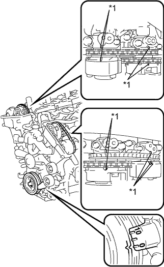
Text in Illustration *1 Timing Mark Remove the cylinder head cover sub-assemblies RH and LH.
-
Turn the crankshaft to align the timing marks of the crankshaft.
-
Align the notch of the crankshaft pulley to the "0" position.
-
Check if the timing marks of the camshaft pulley and camshaft bearing cap align.
-
Turn the crankshaft clockwise 360° if the timing marks do not align. Check if they align once again.
OK The timing marks of the camshaft pulley and the camshaft bearing cap align when the notch of the crankshaft pulley is in the "0" position. -
Reinstall the cylinder head cover sub-assemblies RH and LH.
NG
ADJUST VALVE TIMING Click here
OK
-
-
INSPECT CAMSHAFT TIMING OIL CONTROL VALVE ASSEMBLY (FOR INTAKE CAMSHAFT)
-
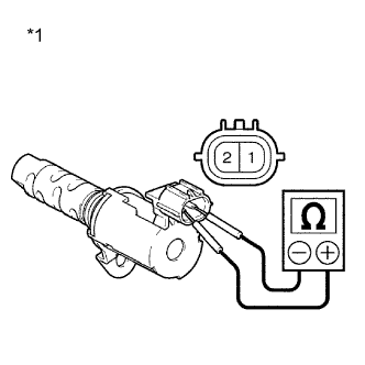
Remove the camshaft timing oil control valve assembly for intake camshaft.
-
Measure the resistance according to the value(s) in the table below.
Standard Resistance Tester Connection Condition Specified Condition 1 - 2 20°C (68°F) 6.9 to 7.9 Ω Text in Illustration *1 Component without harness connected
(Camshaft Timing Oil Control Valve Assembly for Intake Camshaft)
-
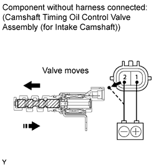
Connect the positive (+) battery terminal to terminal 1 and connect the negative (-) battery terminal to terminal 2. Check the valve operation.
OK Valve moves quickly. -
Reinstall the camshaft timing oil control valve assembly for intake camshaft.
NG
REPLACE CAMSHAFT TIMING OIL CONTROL VALVE ASSEMBLY (FOR INTAKE CAMSHAFT) Click here
OK
-
-
INSPECT OIL CONTROL VALVE FILTER AND OIL PIPE
-
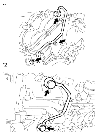
Text in Illustration *1 Bank 1 *2 Bank 2 Remove the No. 1 oil pipe or No. 2 oil pipe.
-
Remove the oil control valve filter RH or oil control valve filter LH.
-
Check that the oil control valve filter and oil pipe are not clogged.
OK The oil control valve filter and oil pipe are not clogged. -
Reinstall the oil control valve filter RH or oil control valve filter LH.
-
Reinstall the No. 1 oil pipe or No. 2 oil pipe.
NG
REPLACE OIL CONTROL VALVE FILTER OR OIL PIPE
OK
-
-
REPLACE CAMSHAFT TIMING GEAR ASSEMBLY
-
Replace the camshaft timing gear assembly (bank 1 or bank 2) Click here.
NEXT
-
-
CHECK WHETHER DTC OUTPUT RECURS
-
Connect the intelligent tester to the DLC3.
-
Turn the engine switch on (IG).
-
Turn the tester on.
-
Clear the DTC Click here.
-
Drive the vehicle for more than 10 minutes.
-
Enter the following menus: Powertrain / Engine / DTC / Pending.
-
Read the pending DTCs.
Result Result Proceed to DTC is not output A DTC P0011, P0012, P0021 or P0022 is output B
B
REPLACE ECM Click here
A
END
-