- Click here
INSTALL AIR FUEL RATIO SENSOR
-
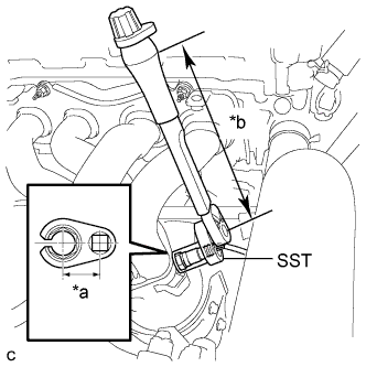
Using SST, install the air fuel ratio sensor to the exhaust manifold.
09224-00010 without SST 44 N*m 449 kgf*cm 32 ft.*lbf with SST 40 N*m 408 kgf*cm 30 ft.*lbf Note:
-
The "with SST" torque value is effective when using SST with a fulcrum length of 30 mm (1.18 in.).
-
The "with SST" torque value is effective when using a torque wrench with a fulcrum length of 300 mm (11.81 in.).
-
This torque value is effective when SST is parallel to the torque wrench.
Table 1. Text in Illustration *a Fulcrum Length
30 mm
*b Fulcrum Length
300 mm
-
-
Install the No. 1 exhaust manifold heat insulator with the 4 bolts.
-
Connect the air fuel ratio sensor connector.
-
Install the wire harness clamp.
-
- Click here
INSTALL NO. 2 AIR CLEANER INLET
-
Install the No. 2 air cleaner inlet with the bolt.
8.0 N*m 82 kgf*cm 71 in.*lbf
-
- Click here
INSPECT FOR EXHAUST GAS LEAK
- Click here
INSTALL NO. 1 ENGINE COVER SUB-ASSEMBLY
-
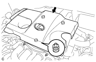
Fit the 3 retainers and install the No. 1 engine cover sub-assembly.
-
- Click here
INSTALL COOL AIR INTAKE DUCT SEAL
-
Install the cool air intake duct seal with the 6 clips.
-
- Click here
INSTALL ENGINE ROOM SIDE COVER LH
-
Engage the guide.
-
Install the engine room side cover LH with the 4 clips.
-
- Click here
INSTALL ENGINE ROOM SIDE COVER
-
Engage the guide.
-
Install the engine room side cover with the 4 clips.
-