SFI SYSTEM, Diagnostic DTC:P0705

| DTC Code | DTC Name |
|---|---|
| P0705 | Transmission Range Sensor Circuit Malfunction (PRNDL Input) |
DESCRIPTION
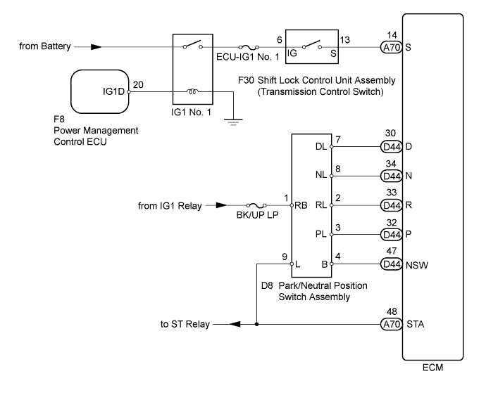
The park/neutral position switch assembly detects the shift lever position and sends signals to the ECM.
| DTC No. | DTC Detection Condition | Trouble Area |
|---|---|---|
| P0705 | (A) 2 or more of the following signals are on simultaneously (2 trip detection logic):
(B) Any of the following conditions is met for 2.0 seconds or more in S (2 trip detection logic):
(C) All switches are off simultaneously for NSW, P, R, N and D. (2 trip detection logic) |
|
WIRING DIAGRAM
INSPECTION PROCEDURE
Note
Inspect the fuses for circuits related to this system before performing the following inspection procedure.
Tech Tips
Using the intelligent tester to read the Data List allows the values or states of switches, sensors, actuators and other items to be read without removing any parts. This non-intrusive inspection can be very useful because intermittent conditions or signals may by discovered before parts or wiring is disturbed. Reading the Data List information early in troubleshooting is one way to save diagnostic time.
-
DATA LIST
Note
In the table below, the values listed under "Normal Condition" are reference values. Do not depend solely on these reference values when deciding whether a part is faulty or not.
-
Warm up the engine.
-
Turn the engine switch off.
-
Connect the intelligent tester to the DLC3.
-
Turn the engine switch on (IG).
-
Turn the tester on.
-
Enter the following menus: Powertrain / Engine / Data List / All Data.
-
Read the values displayed on the tester.
Tester Display Measurement Item/Range Normal Condition Diagnostic Note Shift SW Status (R Range) Park/neutral position switch assembly status:
ON or OFF
-
ON: Shift lever in R
-
OFF: Shift lever not in R
When shift lever position displayed on intelligent tester differs from actual position, adjustment of park/neutral position switch assembly or shift cable may be incorrect Shift SW Status (P Range) Park/neutral position switch assembly status:
ON or OFF
-
ON: Shift lever in P
-
OFF: Shift lever not in P
When shift lever position displayed on intelligent tester differs from actual position, adjustment of park/neutral position switch assembly or shift cable may be incorrect Shift SW Status (N Range) Park/neutral position switch assembly status:
ON or OFF
-
ON: Shift lever in N
-
OFF: Shift lever not in N
When shift lever position displayed on intelligent tester differs from actual position, adjustment of park/neutral position switch assembly or shift cable may be incorrect Shift SW Status (D Range) Park/neutral position switch assembly status:
ON or OFF
-
ON: Shift lever in D or S
-
OFF: Shift lever not in D or S
When shift lever position displayed on intelligent tester differs from actual position, adjustment of park/neutral position switch assembly or shift cable may be incorrect Sports Mode Selection SW Sport mode select switch status:
ON or OFF
-
ON: Shift lever in S, "+" or "-"
-
OFF: Shift lever not in S, "+" and "-"
- -
-
PROCEDURE
-
READ VALUE USING INTELLIGENT TESTER
-
Connect the intelligent tester to the DLC3.
-
Turn the engine switch on (IG).
-
Turn the tester on.
-
Enter the following menus: Powertrain / Engine / Data List / All Data.
-
Read the values displayed on the tester.
OK Tester Display Shift Lever Specified Condition Neutral Position SW Signal P or N ON Except P or N OFF Shift SW Status (R Range) R ON Except R OFF Shift SW Status (P Range) P ON Except P OFF Shift SW Status (N Range) N ON Except N OFF Shift SW Status (D Range) D or S ON Except D or S OFF
NG 
CHECK HARNESS AND CONNECTOR (PARK/NEUTRAL POSITION SWITCH ASSEMBLY VOLTAGE) Click here
OK 
-
-
READ VALUE USING INTELLIGENT TESTER (SPORTS MODE SELECTION SW)
-
Connect the intelligent tester to the DLC3.
-
Turn the engine switch on (IG).
-
Turn the tester on.
-
Enter the following menus: Powertrain / Engine / Data List / All Data / Sports Mode Selection SW.
-
Read the values displayed on the tester.
OK Tester Display Shift Lever Specified Condition Sports Mode Selection SW S ON Except S OFF
NG
INSPECT SHIFT LOCK CONTROL UNIT ASSEMBLY (TRANSMISSION CONTROL SWITCH) Click here
OK 
CHECK FOR INTERMITTENT PROBLEMS Click here
-
-
INSPECT SHIFT LOCK CONTROL UNIT ASSEMBLY (TRANSMISSION CONTROL SWITCH)
-
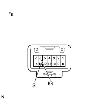
Text in Illustration *a Component without harness connected
(Transmission Control Switch)
Disconnect the transmission control switch connector.
-
Measure the resistance according to the value(s) in the table below.
Standard Resistance Tester Connection Condition Specified Condition 6 (IG) - 13 (S) Shift lever in S, "+" or "-" Below 1 Ω Shift lever in any position other than S, "+" or "-" 10 kΩ or higher -
Reconnect the transmission control switch connector.
NG 
REPLACE SHIFT LOCK CONTROL UNIT ASSEMBLY (TRANSMISSION CONTROL SWITCH) Click here
OK
REPAIR OR REPLACE HARNESS OR CONNECTOR (ECM - TRANSMISSION CONTROL SWITCH)
-
-
CHECK HARNESS AND CONNECTOR (PARK/NEUTRAL POSITION SWITCH ASSEMBLY VOLTAGE)
-
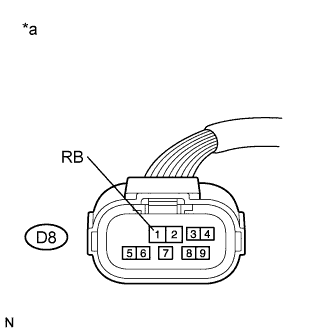
Text in Illustration *a Front view of wire harness connector
(to Park/Neutral Position Switch Assembly)
Disconnect the park/neutral position switch assembly connector.
-
Turn the engine switch on (IG).
-
Measure the voltage according to the value(s) in the table below.
Standard Voltage Tester Connection Condition Specified Condition D8-1 (RB) - Body ground Engine switch on (IG) 11 to 14 V -
Reconnect the park/neutral position switch assembly connector.
NG
REPAIR OR REPLACE HARNESS OR CONNECTOR (PARK/NEUTRAL POSITION SWITCH ASSEMBLY - IG1 RELAY)
OK
-
-
INSPECT PARK/NEUTRAL POSITION SWITCH ASSEMBLY
-
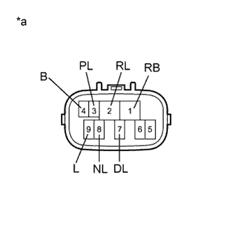
Text in Illustration *a Component without harness connected
(Park/Neutral Position Switch Assembly)
Disconnect the park/neutral position switch assembly connector.
-
Measure the resistance according to the value(s) in the table below.
Standard Resistance Tester Connection Condition Specified Condition 1 (RB) - 3 (PL)
4 (B) - 9 (L)
Shift lever in P Below 1 Ω Shift lever in any position other than P 10 kΩ or higher 1 (RB) - 2 (RL) Shift lever in R Below 1 Ω Shift lever in any position other than R 10 kΩ or higher 1 (RB) - 8 (NL)
4 (B) - 9 (L)
Shift lever in N Below 1 Ω Shift lever in any position other than N 10 kΩ or higher 1 (RB) - 7 (DL) Shift lever in D or S Below 1 Ω Shift lever in any position other than D or S 10 kΩ or higher -
Reconnect the park/neutral position switch assembly connector.
NG
REPLACE PARK/NEUTRAL POSITION SWITCH ASSEMBLY Click here
OK
-
-
CHECK HARNESS AND CONNECTOR (ECM - PARK/NEUTRAL POSITION SWITCH ASSEMBLY)
-

Text in Illustration *a Front view of wire harness connector
(to ECM)
Disconnect the ECM connector.
-
Turn the engine switch on (IG).
-
Measure the voltage according to the value(s) in the table below.
Standard Voltage Tester Connection Condition Specified Condition D44-32 (P) - Body ground
-
Engine switch on (IG)
-
Shift lever in P
11 to 14 V
-
Engine switch on (IG)
-
Shift lever in any position other than P
0 to 1.5 V D44-33 (R) - Body ground
-
Engine switch on (IG)
-
Shift lever in R
11 to 14 V
-
Engine switch on (IG)
-
Shift lever in any position other than R
0 to 1.5 V D44-34 (N) - Body ground
-
Engine switch on (IG)
-
Shift lever in N
11 to 14 V
-
Engine switch on (IG)
-
Shift lever in any position other than N
0 to 1.5 V D44-30 (D) - Body ground
-
Engine switch on (IG)
-
Shift lever in D or S
11 to 14 V
-
Engine switch on (IG)
-
Shift lever in any position other than D or S
0 to 1.5 V -
-
Reconnect the ECM connector.
NG
REPAIR OR REPLACE HARNESS OR CONNECTOR (ECM - PARK/NEUTRAL POSITION SWITCH ASSEMBLY)
OK
-
-
CHECK HARNESS AND CONNECTOR (PARK/NEUTRAL POSITION SWITCH ASSEMBLY - ECM)
-
Disconnect the park/neutral position switch assembly connector.
-
Disconnect the ECM connector.
-
Measure the resistance according to the value(s) in the table below.
Standard Resistance (Check for Open) Tester Connection Condition Specified Condition D8-4 (B) - D44-47 (NSW) Always Below 1 Ω Standard Resistance (Check for Short) Tester Connection Condition Specified Condition D8-4 (B) or D44-47 (NSW) - Body ground Always 10 kΩ or higher -
Reconnect the ECM connector.
-
Reconnect the park/neutral position switch assembly connector.
NG
REPAIR OR REPLACE HARNESS OR CONNECTOR (ECM - PARK/NEUTRAL POSITION SWITCH ASSEMBLY)
OK
REPLACE ECM Click here
-