ECM INSTALLATION

-
INSTALL ECM
-
Install the 2 ECM brackets to the ECM with the 5 screws.
-
Install the ECM with the 3 bolts.
- Torque:
- 8.0 N*m { 82 kgf*cm, 70 in.*lbf }
-
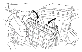
Connect the 2 ECM connectors and lower the 2 levers.
Note
-
When connecting the connectors, make sure that dirt, water or other foreign matter does not become stuck between the connectors and other part.
-
Make sure that the 2 levers are securely locked.
-
-
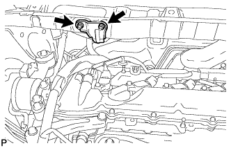
Connect the wire harness clamp.
-
-
INSTALL AIR CLEANER ASSEMBLY
-

Text in Illustration *a A side view *b Front of the vehicle *c 11 to 14 mm (0.433 to 0.551 in.) Install the air cleaner hose with the hose clamp.
Note
Install the air cleaner hose clamp so that the orientation is as shown in the illustration.
-

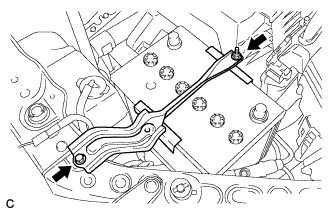
Text in Illustration *a Tab *b Hole Insert the tab of the air cleaner assembly to the hole of the vehicle body as shown in the illustration.
-
Install the air cleaner assembly with the 2 bolts.
- Torque:
- 5.5 N*m { 56 kgf*cm, 49 in.*lbf }
-

Text in Illustration *a Light blue paint mark Connect the vacuum hose to the 2 clamps of the air cleaner hose.
Note
Align the light blue paint mark of the vacuum hose with the clamp of the air cleaner hose.
-
Connect the vacuum hose.
-
Connect the ventilation hose to the cylinder head cover.
-
Connect the vacuum switching valve connector and install the vacuum hose to the 2 clamps.
-
Connect the No. 2 fuel vapor feed hose to the vacuum switching valve and clamp of the air cleaner hose.
-
Connect the mass air flow meter connector and install the wire harness clamp to the air cleaner assembly.
-
Connect the vacuum switching valve connector and install the wire harness clamp to the air cleaner assembly.
-
-
INSTALL BATTERY
-
Install the battery and battery tray.
-
Install the battery clamp with the bolt and nut.
- Torque:
- 5.4 N*m { 55 kgf*cm, 48 in.*lbf }
-
Connect the positive (+) cable to the positive (+) battery terminal.
- Torque:
- 6.4 N*m { 65 kgf*cm, 57 in.*lbf }
-
-
INSTALL NO. 1 AIR CLEANER INLET
-
Install the No. 1 air cleaner inlet with the bolt.
- Torque:
- 8.0 N*m { 82 kgf*cm, 71 in.*lbf }
-
-
INSTALL NO. 2 AIR CLEANER INLET
-
Install the No. 2 air cleaner inlet with the bolt.
- Torque:
- 8.0 N*m { 82 kgf*cm, 71 in.*lbf }
-
-
INSTALL OUTER COWL TOP PANEL SUB-ASSEMBLY (for RHD)
-
Place the front tires on the ground.
-
Remove the 4 nuts used to support the front shock absorber.
-
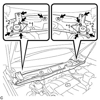
Install the outer cowl top panel sub-assembly with the 4 bolts, 4 nuts*1 and 2 nuts*2.
- Torque:
- Nut*1
- 85 N*m { 866 kgf*cm, 62 ft.*lbf }
- Nut*2
- 5.5 N*m { 56 kgf*cm, 49 in.*lbf }
- Bolt
- 5.5 N*m { 56 kgf*cm, 49 in.*lbf }
-
-
INSTALL OUTER COWL TOP PANEL SUB-ASSEMBLY (for LHD)
-
Place the front tires on the ground.
-
Remove the 4 nuts used to support the front shock absorber.
-
Install the outer cowl top panel sub-assembly with the 4 bolts and 6 nuts.
- Torque:
- Nut*1
- 85 N*m { 866 kgf*cm, 62 ft.*lbf }
- Nut*2
- 5.5 N*m { 56 kgf*cm, 49 in.*lbf }
- Bolt
- 5.5 N*m { 56 kgf*cm, 49 in.*lbf }
-
Engage the grommet and clamp to install the wire harness.
-
Connect the connector (w/ Windshield Deicer).
-
-
INSTALL HOSE BRACKET (for LHD)
-
Install the hose bracket to the outer cowl top panel sub-assembly with the 2 nuts.
- Torque:
- 9.0 N*m { 92 kgf*cm, 80 in.*lbf }
-
-
INSTALL WINDSHIELD WIPER MOTOR AND LINK ASSEMBLY
-
CONNECT CABLE TO NEGATIVE BATTERY TERMINAL
Note
When disconnecting the cable, some systems need to be initialized after the cable is reconnected Click here.
-
INSTALL NO. 1 ENGINE COVER SUB-ASSEMBLY
-
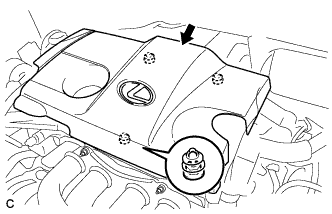
Fit the 3 retainers and install the No. 1 engine cover sub-assembly.
-
-
PERFORM INITIALIZATION
Tech Tips
Initialization cannot be completed by only disconnecting and reconnecting the cable of the negative (-) battery terminal.
-
Perform Initialization when replacing the ECM Click here.
-