POWER BACK DOOR CONTROL SWITCH INSTALLATION

-
INSTALL BACK DOOR CONTROL SWITCH ASSEMBLY
-
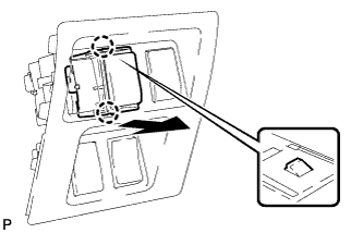
Engage the 2 claws to install the back door control switch assembly as shown in the illustration.
-
-
INSTALL NO. 1 SWITCH HOLE BASE
-
Connect each connector.
-
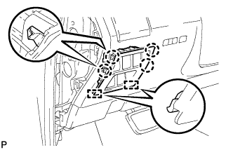
Engage the 4 claws and 2 guides to install the No. 1 switch hole base.
-
-
INSTALL INSTRUMENT PANEL GARNISH LH
-
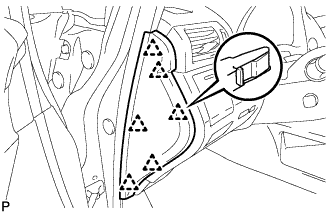
Engage the 6 clips to install the instrument panel garnish LH.
-
-
CONNECT CABLE TO NEGATIVE BATTERY TERMINAL (w/ Air Suspension)
Note
When disconnecting the cable, some systems need to be initialized after the cable is reconnected Click here.
-
INSPECT SUSPENSION CONTROL SYSTEM (w/ Air Suspension)