BACK DOOR DISASSEMBLY

-
REMOVE UPPER BACK WINDOW PANEL TRIM
-
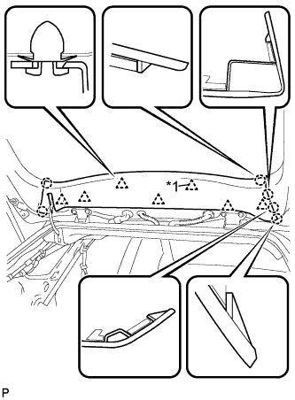
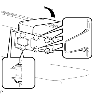
Text in Illustration *1 2-piece Type Clip Disengage the 7 clips and 6 claws, and remove the upper back window panel trim.
Tech Tips
If any clips remain on the back door panel after the upper back window panel trim is removed, remove the clips and install them to the upper back window panel trim.
-
-
REMOVE TONNEAU COVER SUB-ASSEMBLY
-
REMOVE BACK DOOR FINISH COVER LH (w/o Power Back Door)
-
Using a moulding remover, disengage the 6 claws and remove the back door finish cover LH.
-
-
REMOVE BACK DOOR TRIM BASE (w/ Power Back Door)
-
Using a moulding remover, disengage the 4 claws and remove the back door trim base.
-
-
REMOVE BACK DOOR FINISH COVER RH (w/o Power Back Door)
-
Using a moulding remover, disengage the 6 claws and remove the back door finish cover RH.
-
-
REMOVE DOOR PULL HANDLE WITH SWITCH (w/ Power Back Door)
-
Using a moulding remover, disengage the 6 claws and remove the door pull handle with switch.
-
Disconnect the connector.
-
-
REMOVE BACK DOOR LOCK COVER
-
Disengage the 4 claws and remove the back door lock cover.
-
-
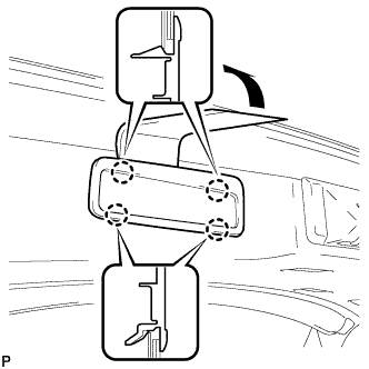
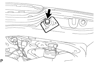
REMOVE NO. 2 ROOM LIGHT ASSEMBLY
-
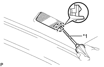
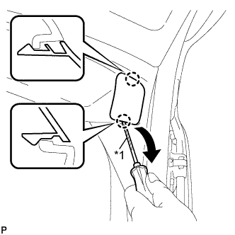
Text in Illustration *1 Protective Tape Using a screwdriver wrapped with protective tape, disengage the claw.
-
Disconnect the connector and remove the No. 2 room light assembly.
-
-
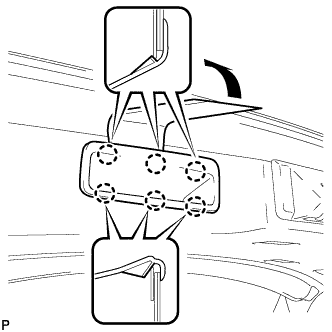
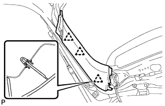
REMOVE BACK DOOR UPPER TRIM COVER LH
-
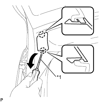
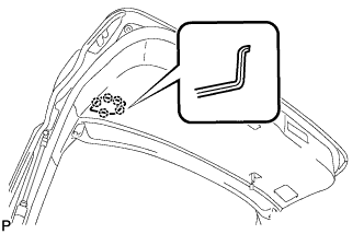
Text in Illustration *1 Protective Tape Using a screwdriver, disengage the 2 claws and remove the back door upper trim cover LH as shown in the illustration.
Tech Tips
Tape the screwdriver tip before use.
-
-
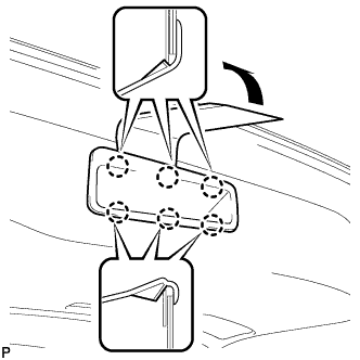
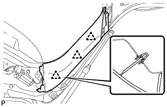
REMOVE BACK DOOR UPPER TRIM COVER RH
-
Text in Illustration *1 Protective Tape Using a screwdriver, disengage the 2 claws and remove the back door upper trim cover LH as shown in the illustration.
Tech Tips
Tape the screwdriver tip before use.
-
-
REMOVE BACK DOOR SERVICE HOLE COVER LH
-
Disengage the 5 claws and remove the back door service hole cover LH.
-
-
REMOVE BACK DOOR SERVICE HOLE COVER RH
-

Disengage the 5 claws and remove the back door service hole cover RH.
-
-
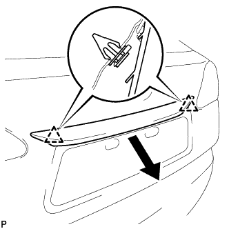
REMOVE BACK DOOR TRIM PANEL ASSEMBLY
-
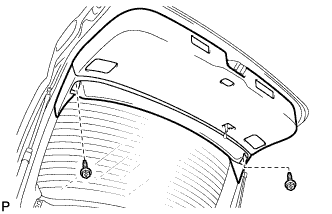
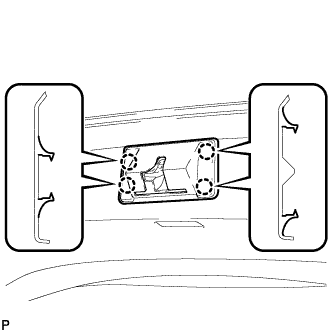
Remove the 2 screws.
-
Grab the service holes by hand.
Note
Make sure to hold the clip bases as shown in the illustration.
-
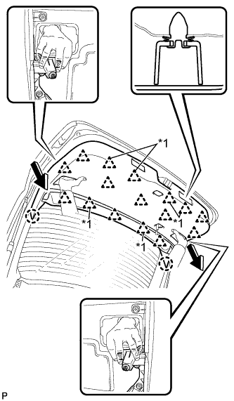
Pull the back door trim panel assembly in the direction shown by the arrows in the illustration (pull perpendicular to the surface of the trim panel) to disengage the 2 claws and 16 clips, and remove the back door trim panel assembly.
Text in Illustration *1 2-piece Type Clip Note
Removing the back door trim panel assembly at an angle may cause deformation or damage. To avoid this, make sure to pull the panel in the direction shown by the arrows (pull perpendicular to the surface of the panel).
Tech Tips
If any clips remain on the back door panel after the back door trim panel assembly is removed, remove the clips and install them to the back door trim panel assembly.
-
-
REMOVE BACK DOOR TRIM COVER LH
-
Disengage the 3 clips and remove the back door trim cover LH.
-
-
REMOVE BACK DOOR TRIM COVER RH
-
Disengage the 3 clips and remove the back door trim cover RH.
-
-
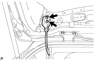
REMOVE BACK DOOR LOCK ASSEMBLY (w/o Power Back Door)
-
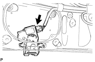
Disconnect the connector.
-
Remove the 3 bolts and back door lock assembly.
-
-
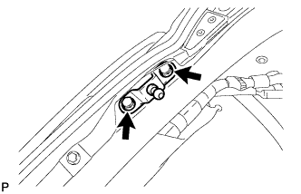
REMOVE BACK DOOR LOCK ASSEMBLY (w/ Power Back Door)
-
Disconnect the connector.
-
Disengage the clamp.
-
Remove the bolt.
-
Remove the 3 bolts and back door lock assembly.
-
-
REMOVE WINDSHIELD HEADER PANEL DAMPER (for 1AR-FE)
-
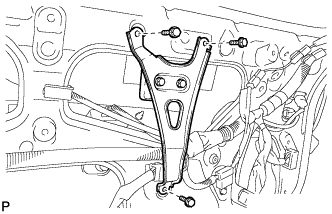
Remove the 3 bolts and back door weight.
-
Remove the 2 bolts and windshield header panel damper from the back door weight retainer.
-
-
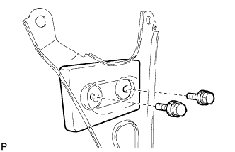
REMOVE LOWER BACK DOOR STOPPER LH
-
Remove the bolt and lower back door stopper LH.
-
-
REMOVE LOWER BACK DOOR STOPPER RH
Tech Tips
Use the same procedure for the RH side and LH side.
-
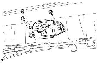
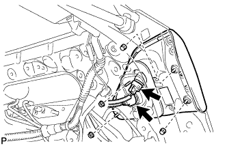
REMOVE POWER BACK DOOR TOUCH SENSOR ASSEMBLY LH (w/ Power Back Door)
-
Disconnect the connector.
-
Remove the 4 screws.
-
Disengage the clip and remove the power back door touch sensor assembly.
-
-
REMOVE POWER BACK DOOR TOUCH SENSOR ASSEMBLY RH (w/ Power Back Door)
Tech Tips
Use the same procedure for the RH side and LH side.
-
DISCONNECT POWER BACK DOOR UNIT ASSEMBLY (w/ Power Back Door)
-
Remove the 2 bolts and disconnect the power back door unit assembly.
-
-
DISCONNECT BACK DOOR STAY ASSEMBLY LH
-
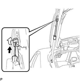
Text in Illustration *1 Protective Tape Using a screwdriver, remove the stop ring along the groove.
Tech Tips
Tape the screwdriver tip before use.
-
Release the ball joint and disengage the back door stay assembly LH.
Note
Remove the back door stay assembly while supporting the back door by hand.
-
-
DISCONNECT BACK DOOR STAY ASSEMBLY RH
Tech Tips
Use the same procedure for the RH side and LH side.
-
REMOVE BACK DOOR LOWER STAY BRACKET LH
-
Remove the 2 bolts and back door lower stay bracket.
-
-
REMOVE BACK DOOR LOWER STAY BRACKET RH
Tech Tips
Use the same procedure for the RH side and LH side.
-
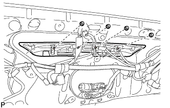
REMOVE AMPLIFIER ANTENNA ASSEMBLY
-
Disconnect the 3 connectors.
-
Remove the 2 bolts.
-
Disengage the 5 clamps and remove the amplifier antenna assembly.
-
-
REMOVE REAR LIGHT ASSEMBLY LH
-
Disconnect each connector.
-
Remove the 4 nuts and rear light assembly.
-
-
REMOVE REAR LIGHT ASSEMBLY RH
Tech Tips
Use the same procedure for the RH side and LH side.
-
REMOVE BACK DOOR OUTSIDE GARNISH SUB-ASSEMBLY
-
Disconnect each connector.
-
Remove the 4 nuts.
-
Disengage the 2 clips and remove the back door outside garnish sub-assembly.
-
Remove the 2 clips and 4 gaskets.
-
Remove the 2 stud bolts.
-
Remove the 2 bolts.
-
-
REMOVE LICENSE PLATE LIGHT ASSEMBLY LH
-
Disconnect the connector.
-
Disengage the 2 claws and remove the license plate light assembly.
-
-
REMOVE LICENSE PLATE LIGHT ASSEMBLY RH
Tech Tips
Use the same procedure for the RH side and LH side.
-
REMOVE REAR TELEVISION CAMERA ASSEMBLY (w/ Rear Monitor)
-
Disconnect the connector.
-
Remove the bolt, nut and rear television camera assembly.
-
-
REMOVE REAR SPOILER SUB-ASSEMBLY
-
Disconnect each connector.
-
Remove the 2 hole plugs.
-
Remove the 5 nuts.
-
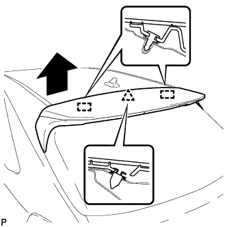
Disengage the clip and 2 pins to remove the rear spoiler sub-assembly.
-
Remove the clip and 2 pins.
-
-
REMOVE REAR WIPER ARM AND BLADE ASSEMBLY
-
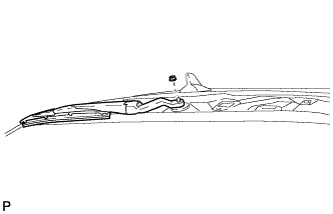
Remove the nut and the rear wiper arm and blade assembly.
-
-
REMOVE REAR WIPER MOTOR GROMMET
-
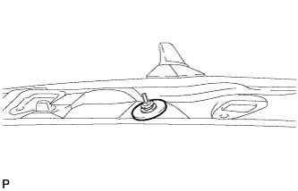
Remove the rear wiper motor grommet.
-
-
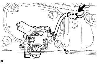
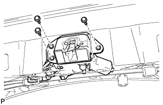
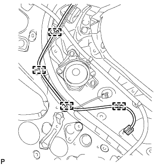
REMOVE REAR WIPER MOTOR AND BRACKET ASSEMBLY
-
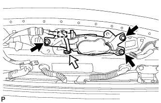
Disconnect the connector.
-
Disengage the clamp.
-
Remove the 3 bolts and the rear wiper motor and bracket assembly.
-
-
REMOVE REAR WASHER NOZZLE
-
Disengage the 2 claws.
-
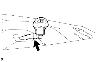
Disconnect the washer hose and remove the rear washer nozzle.
-
-
REMOVE ROOF HEADLINING ASSEMBLY
Tech Tips
Refer to the procedure up to Remove Roof Headlining Assembly Click here.
-
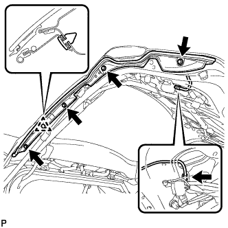
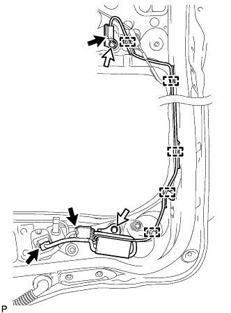
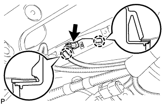
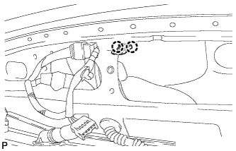
REMOVE NO. 3 ANTENNA CORD SUB-ASSEMBLY
-
Disengage the 4 clamps.
-
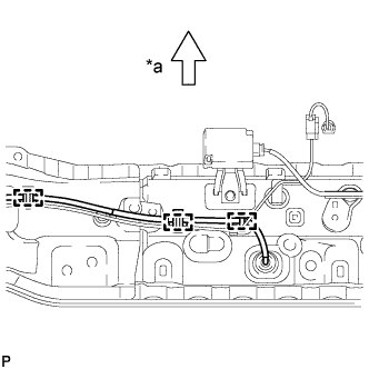
Text in Illustration *a Front Disengage the 3 clamps.
-
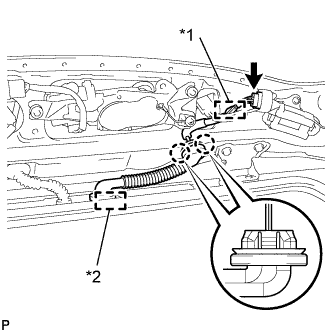
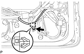
Text in Illustration *1 Clamp *2 Grommet Disconnect the connector.
-
Disengage the clamp.
-
Disconnect the grommet.
-
Disengage the 2 claws and remove the No. 3 antenna cord sub-assembly.
-
-
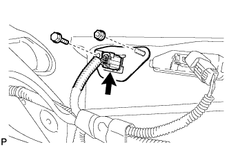
REMOVE RADIO SETTING CONDENSER
Note
When the terminal cover is removed, the radio setting condenser must be replaced because the terminal cover and condenser are supplied as a set.
-
Remove the bolt.
-
Disengage the clamp and remove the radio setting condenser with wire harness from the vehicle body.
-
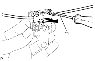
Text in Illustration *1 Protective Tape Using a screwdriver wrapped with protective tape, disengage the 3 claws and remove the terminal cover with wire harness from the condenser.
-
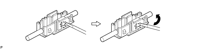
Using a screwdriver, bend back and break off the claw as shown in the illustration.
-
Remove the terminal cover from wire harness.
-