HOOD LOCK CONTROL CABLE ASSEMBLY REMOVAL

-
REMOVE FRONT BUMPER ASSEMBLY
for Sport Package: Click here
for Standard: Click here
-
REMOVE FRONT FENDER TOP REINFORCEMENT SUB-ASSEMBLY LH
-
Text in Illustration *1 Hood to Cowl Top Seal Disengage the clip and the hood to cowl top seal to the front fender top reinforcement sub-assembly LH.
-
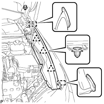
Remove the clip.
-
Disengage the 3 clips and 2 guides, and remove the front fender top reinforcement sub-assembly LH.
-
-
REMOVE FRONT FENDER TOP REINFORCEMENT SUB-ASSEMBLY RH
Tech Tips
Use the same procedure for the RH side and LH side.
-
REMOVE FRONT FENDER TO COWL SIDE SEAL LH
-
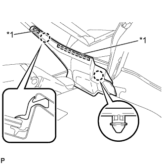
Text in Illustration *1 Double-Sided Tape Disengage the 2 claws and remove the front fender to cowl side seal LH.
-
-
REMOVE FRONT FENDER TO COWL SIDE SEAL RH
Tech Tips
Use the same procedure for the RH side and LH side.
-
REMOVE FRONT WIPER ARM HEAD CAP
-
Text in Illustration *1 Protective Tape Using a screwdriver, disengage the 3 claws and remove the front wiper arm head cap.
Tech Tips
Tape the screwdriver tip before use.
-
-
REMOVE FRONT WIPER ARM AND BLADE ASSEMBLY LH
-
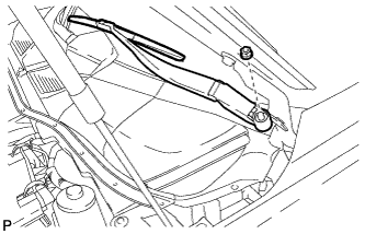
Remove the nut and the front wiper arm and blade assembly LH.
-
-
REMOVE FRONT WIPER ARM AND BLADE ASSEMBLY RH
-
Remove the 2 nuts and the front wiper arm and blade assembly RH.
-
-
REMOVE COWL TOP VENTILATOR LOUVER SUB-ASSEMBLY
-
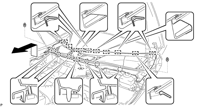
Remove the 2 clips.
-
Disengage the 6 claws and guide <A>.
-
Disengage the 10 guides and pull out the cowl top ventilator louver sub-assembly as shown in the illustration.
-
-
REMOVE WINDSHIELD WIPER MOTOR AND LINK ASSEMBLY
-
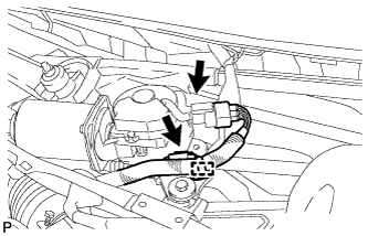
Operate the wiper and stop the windshield wiper motor at the automatic stop position.
-
w/o Deicer:
-
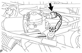
Disconnect the connector.
-
Disengage the clamp.
-
-
w/ Deicer:
-
Disconnect the 2 connectors.
-
Disengage the clamp.
-
-
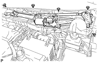
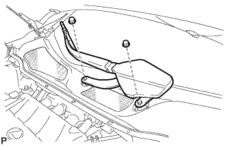
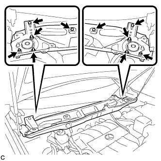
Remove the 5 bolts and the wind shield wiper motor and link assembly as shown in the illustration.
Note
Be careful not to damage the windshield when removing the windshield wiper motor and link assembly.
-
-
REMOVE FRONT SHOCK ABSORBER CAP LH (for LHD)
w/ Air Suspension: Click here
-
REMOVE FRONT SHOCK ABSORBER CAP RH (for LHD)
w/ Air Suspension:
Tech Tips
Use the same procedure for the RH side and LH side.
-
SEPARATE HOSE BRACKET (for LHD)
for 1AR-FE: Click here
-
REMOVE OUTER COWL TOP PANEL SUB-ASSEMBLY (for LHD)
-
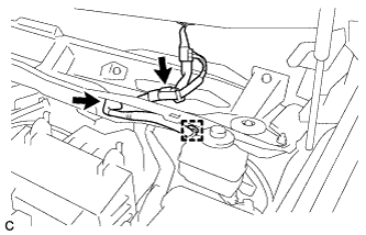
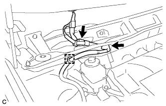
Disconnect the connector (w/ Windshield Deicer).
-
Disengage the grommet and clamp, and separate the wire harness.
-
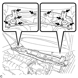
Remove the 6 nuts, 4 bolts and outer cowl top panel sub-assembly.
-
-
REMOVE OUTER COWL TOP PANEL SUB-ASSEMBLY (for RHD)
-
Disconnect the connector (w/ Windshield Deicer).
-
Disengage the grommet and clamp, and separate the wire harness.
-
Remove the 6 nuts, 4 bolts and outer cowl top panel sub-assembly.
-
-
REMOVE MILLIMETER WAVE RADAR SENSOR ASSEMBLY (w/ Dynamic Radar Cruise Control System)
-
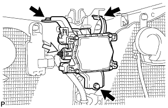
Disconnect the connector.
-
Remove the 3 bolts and the millimeter wave radar sensor assembly.
-
-
REMOVE LOW PITCHED HORN ASSEMBLY (for LHD)
-

Disconnect the connector.
-
Remove the bolt and low pitched horn assembly.
-
-
REMOVE HIGH PITCHED HORN ASSEMBLY (for RHD)
-

Disconnect the connector.
-
Remove the bolt and high pitched horn assembly.
-
-
REMOVE SMOG VENTILATION SENSOR (for RHD)
-

Disconnect the connector.
-
Remove the bolt
-
Disengage the guide and remove the smog ventilation sensor.
-
-
REMOVE HOOD LOCK CONTROL CABLE COVER (for LHD)
-

Remove the 3 screws.
-
Disengage the clamp and remove the hood lock control cable cover.
-
-
REMOVE HOOD LOCK CONTROL CABLE COVER (for RHD)
-

Remove the 3 screws.
-
Disengage the clamp and remove the hood lock control cable cover.
-
-
REMOVE HOOD LOCK ASSEMBLY (for LHD)
-

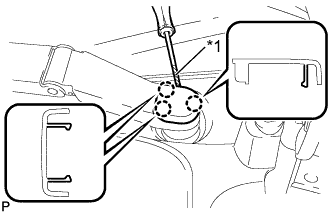
Text in Illustration *1 Protective Tape Using a screwdriver, remove the hood lock nut cap.
Tech Tips
Tape the screwdriver tip before use.
-

Remove the 2 bolts and hood lock nut.
-

Disconnect the connector.
-
Disconnect the hood lock control cable and remove the hood lock assembly.
-
-
REMOVE HOOD LOCK ASSEMBLY (for RHD)
-

Text in Illustration *1 Protective Tape Using a screwdriver, remove the hood lock nut cap.
Tech Tips
Tape the screwdriver tip before use.
-

Remove the 2 bolts and hood lock nut.
-

Disconnect the connector.
-
Disconnect the hood lock control cable and remove the hood lock assembly.
-
-
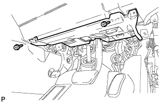
REMOVE NO. 1 INSTRUMENT PANEL UNDER COVER SUB-ASSEMBLY (for LHD)
-
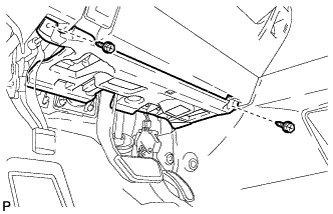
Remove the 2 screws <D>.
-
Disengage the claw and 2 guides as shown in the illustration.
-
Disconnect each connector.
-
Disengage each clamp and remove the No. 1 instrument panel under cover sub-assembly.
-
-
REMOVE NO. 1 INSTRUMENT PANEL UNDER COVER SUB-ASSEMBLY (for RHD)
-
Remove the 2 screws <D>.
-
Disengage the claw and 2 guides as shown in the illustration.
-
Disconnect each connector.
-
Disengage each clamp and remove the No. 1 instrument panel under cover sub-assembly.
-
-
REMOVE HOOD LOCK CONTROL LEVER SUB-ASSEMBLY
-
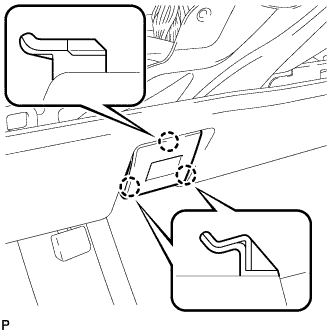
Disengage the 3 claws.
-
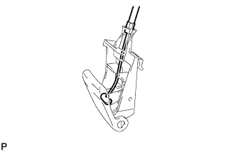
Remove the hood lock control cable assembly and hood lock control lever sub-assembly.
-
-
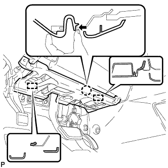
REMOVE HOOD LOCK CONTROL CABLE ASSEMBLY (for LHD)
-
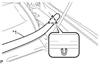
Using a screwdriver, disconnect the clamps shown in the illustration.
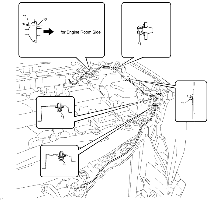
Text in Illustration *1 Hood Lock Control Cable *2 Stopper Tech Tips
Tape the screwdriver tip before use.
-
Pull the hood lock control cable assembly from the engine compartment and remove it.
-
-
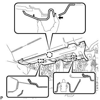
REMOVE HOOD LOCK CONTROL CABLE ASSEMBLY (for RHD)
-
Using a screwdriver, disconnect the clamps shown in the illustration.
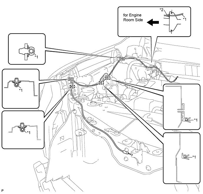
Text in Illustration *1 Hood Lock Control Cable *2 Stopper Tech Tips
Tape the screwdriver tip before use.
-
Pull the hood lock control cable assembly from the engine compartment and remove it.
-