2GR-FE COMPRESSOR REMOVAL

-
PRECAUTION
-
w/ Air Suspension:
Note
Be sure to read Precaution thoroughly before servicing Click here.
-
w/ Navigation System for HDD:
Note
w/ Navigation System for HDD:After the engine switch is turned off, the display and navigation module display (HDD navigation system) records various types of memory and settings. As a result, after turning the engine switch off, make sure to wait for the time specified in the following table before disconnecting the cable from the negative (-) battery terminal.
Waiting Time before Disconnecting Cable from Negative (-) Battery Terminal Specification Waiting Time w/o Telematics transceiver 60 sec. w/ Telematics transceiver 120 sec.
-
-
RECOVER REFRIGERANT FROM REFRIGERATION SYSTEM
-
Start up the engine.
-
Turn the A/C switch on.
-
Operate the cooler compressor at an engine speed of approximately 1000 rpm for 5 to 6 minutes to circulate the refrigerant. This causes most of the compressor oil from the various components of the A/C system to collect in the A/C compressor.
-
Stop the engine.
-
Recover the refrigerant from the A/C system using a refrigerant recovery unit.
-
-
DISCONNECT CABLE FROM NEGATIVE BATTERY TERMINAL
Note
When disconnecting the cable, some systems need to be initialized after the cable is reconnected Click here.
-
REMOVE FRONT WHEEL RH
-
REMOVE FRONT FENDER LINER RH
-

Using a screwdriver, turn the pin 90 degrees and remove the 2 pin hold clips.
-

Using a 4 mm hexagon wrench, remove the 4 hexagon screws.
-

Text in Illustration *1 Grommet Remove the 7 clips and 6 screws.
-
Remove the 3 grommets and front fender liner RH.
Tech Tips
The grommets need to be replaced with new ones because they will break when they are removed.
-
-
REMOVE FRONT FENDER APRON SEAL RH
-
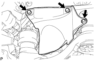
Remove the 2 bolts, clip and front fender apron seal RH.
-
-
REMOVE V-RIBBED BELT
-
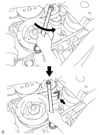
Release the V-ribbed belt tension by turning the V-ribbed belt tensioner counterclockwise, and remove the V-ribbed belt from the V-ribbed belt tensioner.
-
While turning the V-ribbed belt tensioner counterclockwise, align with its holes, and then insert a 5 mm bi-hexagon wrench into the holes to fix the V-ribbed belt tensioner.
-
-
REMOVE NO. 1 ENGINE UNDER COVER
-
DRAIN ENGINE COOLANT
CAUTION:
Do not remove the radiator cap sub-assembly, cylinder block drain cock plugs or radiator drain cock plug while the engine and radiator assembly are still hot. Pressurized, hot engine coolant and steam may be released and cause serious burns.
-
Loosen the radiator drain cock plug.
-
Loosen the cylinder block drain cock plug. (for Bank 1)
-
Loosen the cylinder block drain cock plug. (for Bank 2, w/ Cylinder Block Drain Cock Plug)
-
Remove the radiator cap sub-assembly.
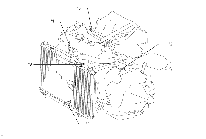
Text in Illustration *1 Radiator Cap Sub-assembly *2 Cylinder Block Drain Cock Plug (for Bank 1) *3 Cylinder Block Drain Cock Plug (for Bank 2, w/ Cylinder Block Drain Cock Plug) *4 Radiator Drain Cock Plug *5 Air Drain Cock Plug - - Tech Tips
Collect the engine coolant in a container and dispose of it according to the regulations in your area.
-
-
REMOVE V-BANK COVER SUB-ASSEMBLY
-
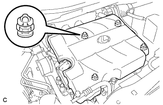
Hold the front of the V-bank cover sub-assembly and raise it to disengage the 2 retainers on the front of the V-bank cover sub-assembly. Continue to raise the V-bank cover sub-assembly to disengage the 2 retainers on the rear of the V-bank cover sub-assembly and remove the V-bank cover sub-assembly.
Note
Attempting to disengage both front and rear retainers at the same time may cause the V-bank cover sub-assembly to break.
-
-
REMOVE FRONT BUMPER ASSEMBLY
for Standard: Click here
for Sport Package: Click here
-
REMOVE MILLIMETER WAVE RADAR SENSOR ASSEMBLY (w/ Dynamic Radar Cruise Control System)
-
Disconnect the connector.
-
Remove the 3 bolts and the millimeter wave radar sensor assembly.
-
-
REMOVE LOW PITCHED HORN ASSEMBLY
-

Disconnect the connector.
-
Remove the bolt and low pitched horn assembly.
-
-
REMOVE HOOD LOCK CONTROL CABLE COVER (for LHD)
-

Remove the 3 screws.
-
Disengage the clamp and remove the hood lock control cable cover.
-
-
REMOVE HOOD LOCK CONTROL CABLE COVER (for RHD)
-

Remove the 3 screws.
-
Disengage the clamp and remove the hood lock control cable cover.
-
-
REMOVE HOOD LOCK ASSEMBLY (for LHD)
-

Text in Illustration *1 Protective Tape Using a screwdriver, remove the hood lock nut cap.
Tech Tips
Tape the screwdriver tip before use.
-

Remove the 2 bolts and hood lock nut.
-

Disconnect the connector.
-
Disconnect the hood lock control cable and remove the hood lock assembly.
-
-
REMOVE HOOD LOCK ASSEMBLY (for RHD)
-

Text in Illustration *1 Protective Tape Using a screwdriver, remove the hood lock nut cap.
Tech Tips
Tape the screwdriver tip before use.
-

Remove the 2 bolts and hood lock nut.
-

Disconnect the connector.
-
Disconnect the hood lock control cable and remove the hood lock assembly.
-
-
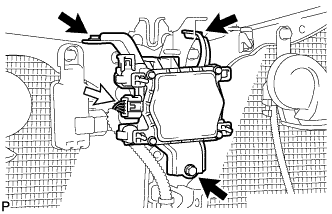
REMOVE HIGH PITCHED HORN ASSEMBLY
-

Disconnect the connector.
-
Remove the bolt and high pitched horn assembly.
-
-
REMOVE SMOG VENTILATION SENSOR (w/ Smog Ventilation Sensor)
-

Disconnect the connector.
-
Remove the bolt
-
Disengage the guide and remove the smog ventilation sensor.
-
-
REMOVE HOOD LOCK SUPPORT SUB-ASSEMBLY
-

Disengage each clamp.
-
Remove the 2 bolts and hood lock support sub-assembly.
-
-
REMOVE NO. 2 AIR CLEANER INLET
-
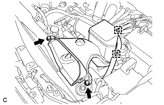
Disconnect the 2 vacuum hose clamps from the No. 2 air cleaner inlet.
-
Remove the 2 bolts and No. 2 air cleaner inlet.
-
-
REMOVE NO. 1 AIR CLEANER INLET
-
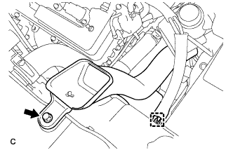
Disconnect the vacuum hose clamp from the No. 1 air cleaner inlet.
-
Remove the bolt and No. 1 air cleaner inlet.
-
-
REMOVE BATTERY
-
Disconnect the positive (+) cable from the positive (+) battery terminal.
-
Loosen the nut, and remove the bolt from the battery clamp.
-
Remove the battery and battery tray.
-
-
DISCONNECT DISCHARGE TUBE SUB-ASSEMBLY
-

Remove the bolt and disconnect the discharge tube sub-assembly.
-
Remove the O-ring from the discharge tube sub-assembly.
Note
Seal the openings of the disconnected parts using vinyl tape to prevent entry of moisture and foreign matter.
-
-
DISCONNECT AIR CONDITIONING TUBE AND ACCESSORY ASSEMBLY
-

Remove the bolt and disconnect the air conditioning tube and accessory assembly.
-
Remove the O-ring from the air conditioning tube and accessory assembly.
Note
Seal the openings of the disconnected parts using vinyl tape to prevent entry of moisture and foreign matter.
-
-
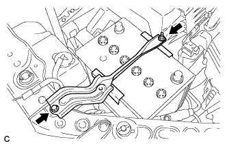
REMOVE RADIATOR RESERVE TANK ASSEMBLY
-

Disconnect the radiator reserve tank hose from the radiator.
-

Disconnect the 2 clamps and remove the bolt and radiator reserve tank from the radiator.
-
-
DISCONNECT NO. 1 RADIATOR HOSE
-

Disconnect the No. 1 radiator hose from the radiator.
-
-
DISCONNECT NO. 2 RADIATOR HOSE
-

Disconnect the No. 2 radiator hose from the radiator.
-
-
DISCONNECT INLET OIL COOLER HOSE
-

Disconnect the inlet oil cooler hose and clamp from the radiator.
-
-
DISCONNECT OUTLET OIL COOLER HOSE
-

Remove the outlet oil cooler hose.
-
-
REMOVE UPPER RADIATOR SUPPORT
-

Disconnect the 3 clamps of the hood lock control cable and remove the 5 bolts and upper radiator support.
-
-
REMOVE COOLER CONDENSER ASSEMBLY
-

Remove the 2 bolts and 2 cooler brackets.
-

Remove the cooler condenser assembly as shown in the illustration.
Note
-
Due to the potential of damaging the brackets, do not allow the brackets to touch the vehicle body etc. while installing the condenser.
-
Do not allow the condenser to contact the vehicle body or radiator while installing the condenser.
-
When storing the condenser, do not put the brackets facing down (toward the ground) because this may cause damage to the brackets.
-
-
-
REMOVE RADIATOR ASSEMBLY AND FAN ASSEMBLY WITH MOTOR
Tech Tips
Refer to the procedure for Remove No. 2 Radiator Assembly Click here.
-
DISCONNECT DISCHARGE HOSE SUB-ASSEMBLY
-

Remove the bolt and disconnect the discharge hose sub-assembly from the compressor and magnetic clutch.
-
Remove the O-ring from the discharge hose sub-assembly.
Note
Seal the openings of the disconnected parts using vinyl tape to prevent entry of moisture and foreign matter.
-
-
DISCONNECT SUCTION HOSE SUB-ASSEMBLY
-

Remove the bolt and disconnect the suction hose sub-assembly from the compressor and magnetic clutch.
-
Remove the O-ring from the suction hose sub-assembly.
Note
Seal the openings of the disconnected parts using vinyl tape to prevent entry of moisture and foreign matter.
-
-
REMOVE COMPRESSOR AND MAGNETIC CLUTCH
-
Disengage each clamp.
-
Disconnect each connector.
-
for Standard Bolt:
-
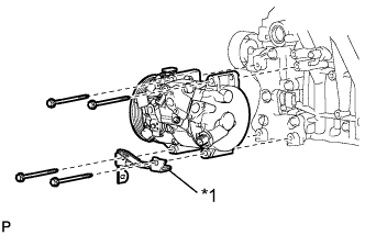
Text in Illustration *1 Bracket Remove the 4 bolts, bracket and the compressor and magnetic clutch.
-
-
for Stud Bolt:
-

Text in Illustration *1 Bracket *2 Nut *3 Stud bolt *4 Bolt Remove the 2 nuts, 2 bolts and bracket.
-
Remove the 2 stud bolts and the compressor and magnetic clutch.
-
-