1AR-FE COMPRESSOR REMOVAL

-
PRECAUTION
-
w/ Air Suspension:
Note
Be sure to read Precaution thoroughly before servicing Click here.
-
w/ Navigation System for HDD:
Note
w/ Navigation System for HDD:After the engine switch is turned off, the display and navigation module display (HDD navigation system) records various types of memory and settings. As a result, after turning the engine switch off, make sure to wait for the time specified in the following table before disconnecting the cable from the negative (-) battery terminal.
Waiting Time before Disconnecting Cable from Negative (-) Battery Terminal Specification Waiting Time w/o Telematics transceiver 60 sec. w/ Telematics transceiver 120 sec.
-
-
RECOVER REFRIGERANT FROM REFRIGERATION SYSTEM
-
Start up the engine.
-
Turn the A/C switch on.
-
Operate the cooler compressor at an engine speed of approximately 1000 rpm for 5 to 6 minutes to circulate the refrigerant. This causes most of the compressor oil from the various components of the A/C system to collect in the A/C compressor.
-
Stop the engine.
-
Recover the refrigerant from the A/C system using a refrigerant recovery unit.
-
-
DISCONNECT CABLE FROM NEGATIVE BATTERY TERMINAL
Note
When disconnecting the cable, some systems need to be initialized after the cable is reconnected Click here.
-
REMOVE FRONT WHEEL RH
-
DISCONNECT FRONT FENDER LINER RH
-

Using a screwdriver, turn the pin 90 degrees and remove the 2 pin hold clips.
-

Using a 4 mm hexagon wrench, remove the 4 hexagon screws.
-

Text in Illustration *1 Grommet Remove the 7 clips and 6 screws.
-
Remove the 3 grommets and front fender liner RH.
Tech Tips
The grommets need to be replaced with new ones because they will break when they are removed.
-
-
REMOVE FRONT FENDER APRON SEAL RH
-
Remove the 2 bolts, clip and front fender apron seal RH.
-
-
REMOVE V-RIBBED BELT
-
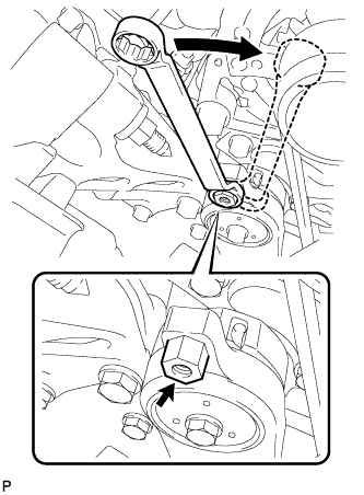
Attach a wrench to the hexagonal portion of the belt tensioner as shown in the illustration, rotate the belt tensioner clockwise, and remove the V-ribbed belt.
-
-
REMOVE NO. 1 ENGINE UNDER COVER
-
DISCONNECT SUCTION HOSE SUB-ASSEMBLY
-
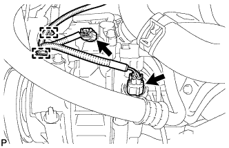
Disengage the 2 clamps.
-
Disengage the 2 connectors.
-
Remove the bolt and disconnect the suction hose sub-assembly from the compressor assembly with pulley.
-
Remove the O-ring from the suction hose sub-assembly.
Note
Seal the openings of the disconnected parts using vinyl tape to prevent entry of moisture and foreign matter.
-
-
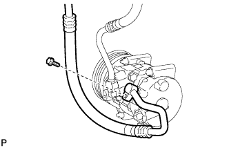
DISCONNECT DISCHARGE HOSE SUB-ASSEMBLY
-
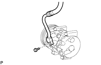
Remove the bolt and disconnect the discharge hose sub-assembly from the compressor assembly with pulley.
-
Remove the O-ring from the discharge hose sub-assembly.
Note
Seal the openings of the disconnected parts using vinyl tape to prevent entry of moisture and foreign matter.
-
-
REMOVE COMPRESSOR ASSEMBLY WITH PULLEY
-
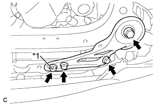
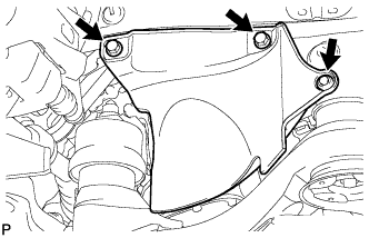
Text in Illustration *1 Nut Remove the 3 bolts, nut and frame side plate RH.
-
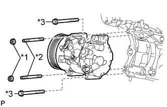
Text in Illustration *1 Nut *2 Stud bolt *3 Bolt Remove the 2 nuts and 2 bolts.
-
Using a "TORX" socket wrench (E8), remove the 2 stud bolts and the compressor assembly with pulley.
-