AIR CONDITIONING UNIT REMOVAL

Note
Make sure to select FACE mode before disconnecting the cable from the negative (-) battery terminal.
-
RECOVER REFRIGERANT FROM REFRIGERATION SYSTEM
-
Start up the engine.
-
Turn the A/C switch on.
-
Operate the cooler compressor at an engine speed of approximately 1000 rpm for 5 to 6 minutes to circulate the refrigerant. This causes most of the compressor oil from the various components of the A/C system to collect in the A/C compressor.
-
Stop the engine.
-
Recover the refrigerant from the A/C system using a refrigerant recovery unit.
-
-
REMOVE FRONT SEAT ASSEMBLY
-
for LH Side: Click here
-
for RH Side:
Tech Tips
Use the same procedure for the RH side and LH side.
-
-
REMOVE ENGINE ROOM SIDE COVER
-
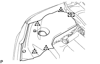
Remove the 4 clips.
-
Disengage the guide and remove the engine room side cover.
-
-
REMOVE ENGINE ROOM SIDE COVER LH
-
Remove the 4 clips.
-
Disengage the guide and remove the engine room side cover LH.
-
-
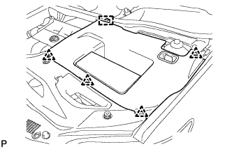
REMOVE COOL AIR INTAKE DUCT SEAL
-
Remove the 6 clips and cool air intake duct seal.
-
-
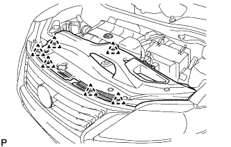
REMOVE FRONT FENDER TOP REINFORCEMENT SUB-ASSEMBLY LH
-
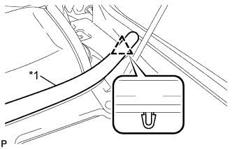
Text in Illustration *1 Hood to Cowl Top Seal Disengage the clip and the hood to cowl top seal to the front fender top reinforcement sub-assembly LH.
-
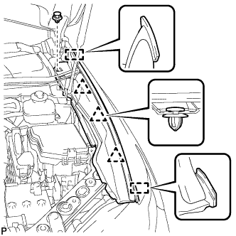
Remove the clip.
-
Disengage the 3 clips and 2 guides, and remove the front fender top reinforcement sub-assembly LH.
-
-
REMOVE FRONT FENDER TOP REINFORCEMENT SUB-ASSEMBLY RH
Tech Tips
Use the same procedure for the RH side and LH side.
-
REMOVE FRONT FENDER TO COWL SIDE SEAL LH
-
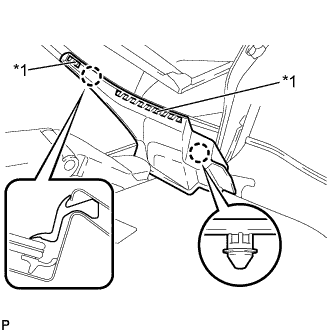
Text in Illustration *1 Double-Sided Tape Disengage the 2 claws and remove the front fender to cowl side seal LH.
-
-
REMOVE FRONT FENDER TO COWL SIDE SEAL RH
Tech Tips
Use the same procedure for the RH side and LH side.
-
REMOVE FRONT WIPER ARM HEAD CAP
-
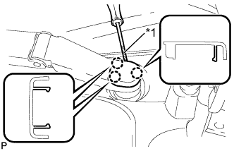
Text in Illustration *1 Protective Tape Using a screwdriver, disengage the 3 claws and remove the front wiper arm head cap.
Tech Tips
Tape the screwdriver tip before use.
-
-
REMOVE FRONT WIPER ARM AND BLADE ASSEMBLY LH
-
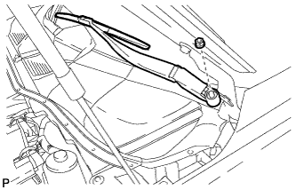
Remove the nut and the front wiper arm and blade assembly LH.
-
-
REMOVE FRONT WIPER ARM AND BLADE ASSEMBLY RH
-
Remove the 2 nuts and the front wiper arm and blade assembly RH.
-
-
REMOVE COWL TOP VENTILATOR LOUVER SUB-ASSEMBLY
-
Remove the 2 clips.
-
Disengage the 6 claws and guide <A>.
-
Disengage the 10 guides and pull out the cowl top ventilator louver sub-assembly as shown in the illustration.
-
-
REMOVE WINDSHIELD WIPER MOTOR AND LINK ASSEMBLY
-
Operate the wiper and stop the windshield wiper motor at the automatic stop position.
-
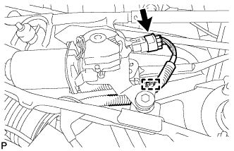
w/o Deicer:
-
Disconnect the connector.
-
Disengage the clamp.
-
-
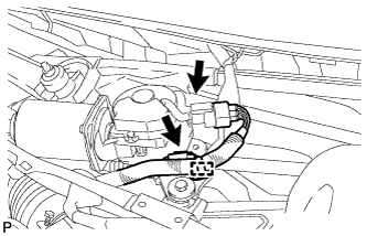
w/ Deicer:
-
Disconnect the 2 connectors.
-
Disengage the clamp.
-
-
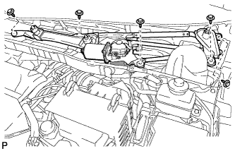
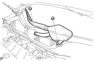
Remove the 5 bolts and the wind shield wiper motor and link assembly as shown in the illustration.
Note
Be careful not to damage the windshield when removing the windshield wiper motor and link assembly.
-
-
REMOVE FRONT SHOCK ABSORBER CAP LH (w/ Air Suspension)
-
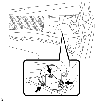
Remove the 3 nuts and the front shock absorber cap.
-
-
REMOVE FRONT SHOCK ABSORBER CAP RH (w/ Air Suspension)
Tech Tips
Use the same procedure for the RH side and LH side.
-
REMOVE OUTER COWL TOP PANEL SUB-ASSEMBLY
for LHD: Click here
for RHD: Click here
-
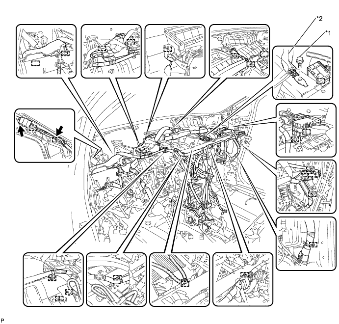
DISCONNECT SUCTION PIPE SUB-ASSEMBLY
-
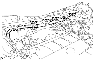
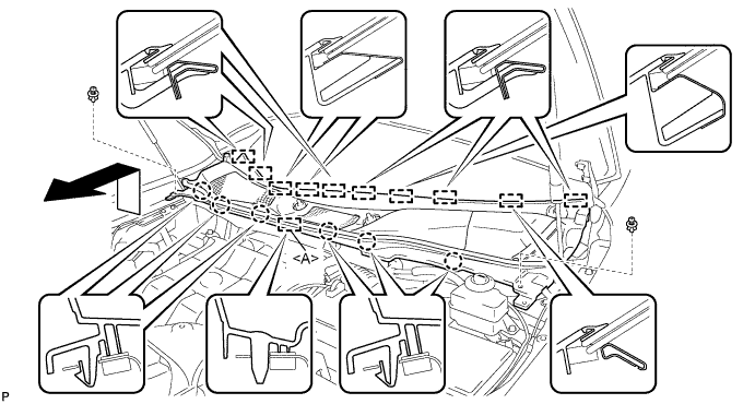
Disengage the 6 clamps and separate the engine wire harness.
-
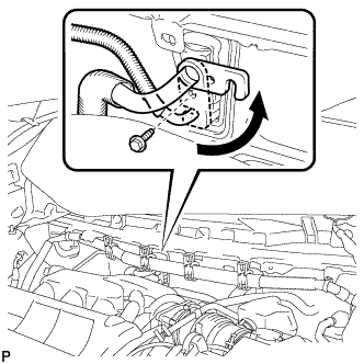
Remove the bolt and slide the hook connector.
-
Disconnect the suction pipe assembly.
-
Remove the O-ring from the suction pipe assembly.
Note
Seal the openings of the disconnected parts using vinyl tape to prevent entry of moisture and foreign matter.
-
-
DISCONNECT AIR CONDITIONING TUBE AND ACCESSORY ASSEMBLY
-
Disconnect the air conditioning tube and accessory assembly.
-
Remove the O-ring from the air conditioning tube and accessory assembly.
Note
Seal the openings of the disconnected parts using vinyl tape to prevent entry of moisture and foreign matter.
-
-
DISCONNECT OUTLET HEATER WATER HOSE
-
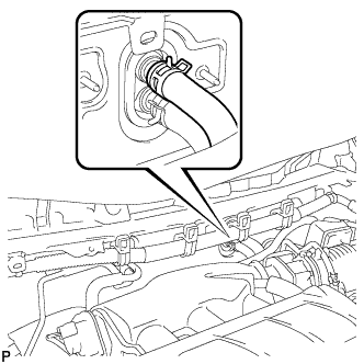
Using pliers, grip the claws of the clip and slide the clip to disconnect the outlet heater water hose.
Note
-
Do not apply excessive force to the outlet heater water hose.
-
Prepare a drain pan or cloth in case the coolant leaks.
-
-
-
DISCONNECT INLET HEATER WATER HOSE
-
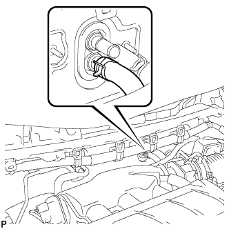
Using pliers, grip the claws of the clip and slide the clip to disconnect the inlet heater water hose.
Note
-
Do not apply excessive force to the inlet heater water hose.
-
Prepare a drain pan or cloth in case the coolant leaks.
-
-
-
REMOVE INSTRUMENT PANEL SAFETY PAD ASSEMBLY
-
REMOVE STEERING POST ASSEMBLY
-
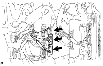
REMOVE INSTRUMENT PANEL JUNCTION BLOCK ASSEMBLY (for LHD)
-
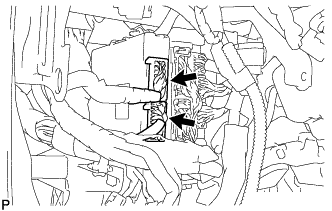
Disconnect the 2 connectors.
-
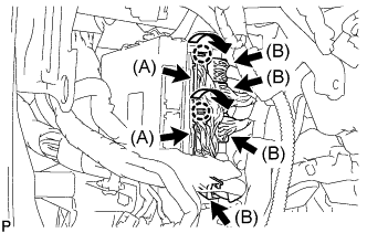
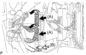
Disengage the 2 claws as shown in the illustration and disconnect the 2 connectors (A).
-
Disconnect the 4 connectors (B).
-
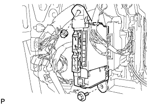
Remove the 2 nuts.
-
Disengage the claw as shown in the illustration and disconnect the connector.
-
Disengage the 2 claws and release the connector lock as shown in the illustration.
-
Disengage the claw as shown in the illustration and disconnect the connector and remove the instrument panel junction block assembly.
-
-
REMOVE INSTRUMENT PANEL JUNCTION BLOCK ASSEMBLY (for RHD)
-
Disconnect the 3 connectors.
-
Disengage the 2 claws as shown in the illustration and disconnect the 2 connectors (A).
-
Disconnect the connector (B).
-
Remove the bolt and nut.
-
Disengage the claw as shown in the illustration and disconnect the connector.
-
Disengage the 2 claws and release the connector lock as shown in the illustration.
-
Disengage the claw as shown in the illustration and disconnect the connector and remove the instrument panel junction block assembly.
-
-
REMOVE POWER STEERING ECU ASSEMBLY
for LHD: Click here
for RHD: Click here
-
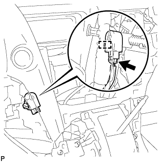
REMOVE TURN SIGNAL FLASHER ASSEMBLY
-
Disengage the clamp.
-
Disconnect the connector and remove the turn signal flasher assembly.
-
-
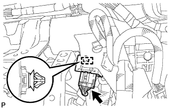
REMOVE CLEARANCE WARNING BUZZER
-
Disconnect the connector.
-
Disengage the clamp and remove the clearance warning buzzer.
-
-
REMOVE ECU INTEGRATION BOX
-
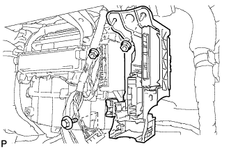
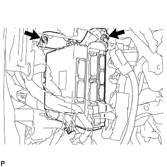
Remove the bolt, 2 nuts and ECU integration box.
-
-
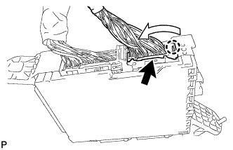
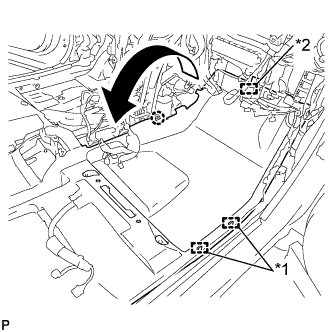
REMOVE REAR NO. 2 AIR DUCT
-
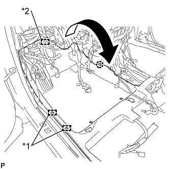
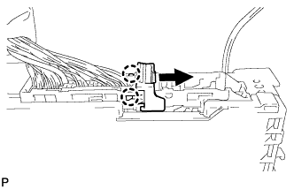
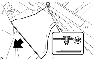
Disengage the 2 clamps and fastener.
-
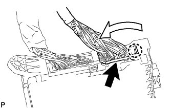
Disengage the claw and turn back the floor carpet as shown in the illustration.
Text in Illustration *1 Clamp *2 Fastener -
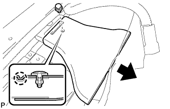
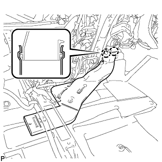
Remove the clip.
-
Disengage the claw and remove the rear No. 2 air duct.
-
-
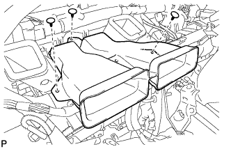
REMOVE REAR NO. 1 AIR DUCT
-
Disengage the clamp.
-
Disengage the 2 claws and remove the rear No. 1 air duct.
-
-
REMOVE FRONT FLOOR CAUTION PLATE COVER
-
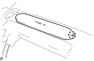
Disengage the claw.
-
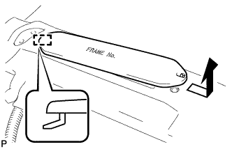
Disengage the guide and remove the frame number cover as shown in the illustration.
-
-
REMOVE REAR NO. 4 AIR DUCT
-
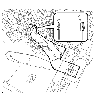
Disengage the 2 clamps and fastener.
-
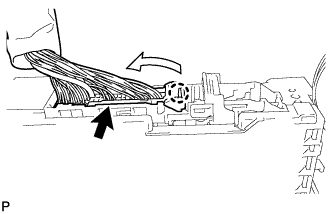
Disengage the claw and turn back the floor carpet as shown in the illustration.
Text in Illustration *1 Clamp *2 Fastener -
Remove the clip.
-
Disengage the claw and remove the rear No. 4 air duct.
-
-
REMOVE REAR NO. 3 AIR DUCT
-
Disengage the 2 claws and remove the rear No. 3 air duct.
-
-
REMOVE CENTER HEATER TO REGISTER SUB DUCT
-
Remove the 3 clips and center heater to register sub duct.
-
-
REMOVE NO. 5 INSTRUMENT PANEL BRACKET
-
Remove the 2 No. 5 instrument panel brackets.
-
-
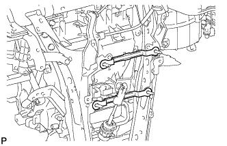
REMOVE NO. 1 INSTRUMENT PANEL BRACE SUB-ASSEMBLY
-
Text in Illustration *1 Screw *2 Bolt *3 Nut Disengage each clamp.
-
Remove the screw.
-
Remove the 2 bolts, 2 nuts and No. 1 instrument panel brace sub-assembly.
-
-
REMOVE NO. 2 INSTRUMENT PANEL BRACE SUB-ASSEMBLY
-
Text in Illustration *1 Screw *2 Bolt *3 Nut Disengage each clamp.
-
Remove the screw.
-
Remove the 2 bolts, 2 nuts and No. 2 instrument panel brace sub-assembly.
-
-
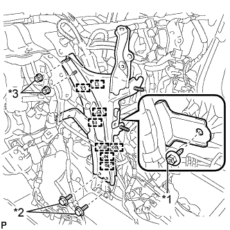
REMOVE INSTRUMENT PANEL REINFORCEMENT ASSEMBLY WITH AIR CONDITIONING UNIT ASSEMBLY
-
Disengage each clamp.
-
Disconnect each connector.
-
Remove the bolt and disconnect the earth wire.
Text in Illustration *1 Bolt *2 Earth wire -
Disengage each clamp.
-
Disconnect the connector.
-
Disconnect the blower motor connector.
-
Disconnect the 2 air conditioning ECU connectors.
-
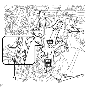
Remove the bolt and disconnect the earth wire.
-
Remove the nut and disconnect the connector holder.
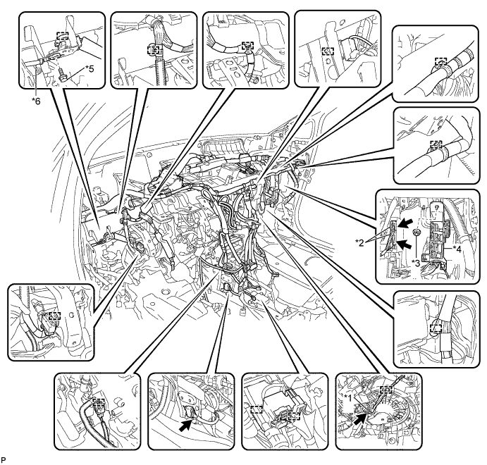
Text in Illustration *1 Blower motor connector *2 Air conditioning ECU connector *3 Nut *4 Connector holder *5 Bolt *6 Earth wire -
Remove the 2 bolts and 2 caps from the engine compartment side.
-
Remove the nut.
-
Disconnect the cooler drain hose.
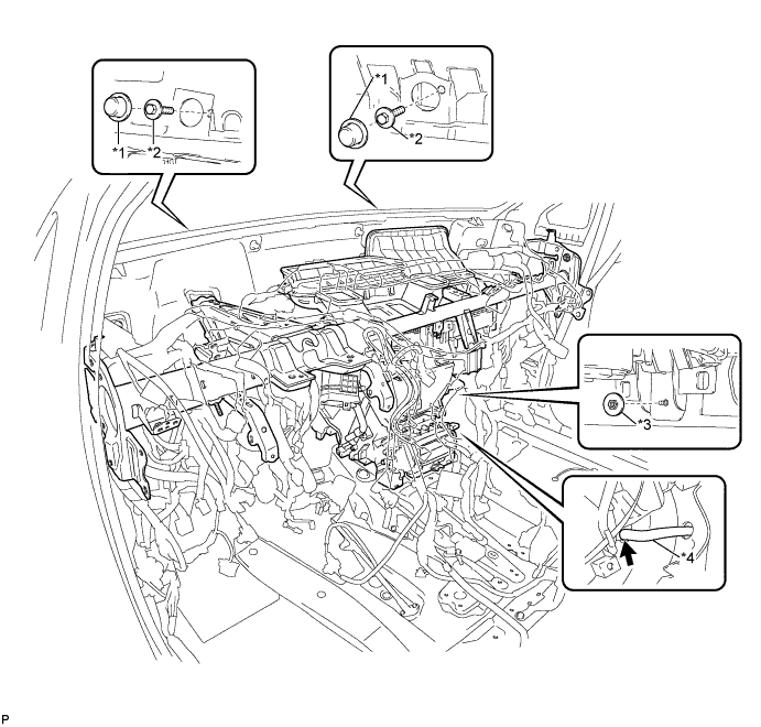
Text in Illustration *1 Cap *2 Bolt *3 Nut *4 Cooler drain hose -
Remove the 5 instrument panel safety pad caps.
-
Using a "TORX" socket wrench (T40), remove the 5 "TORX" bolts and the instrument panel reinforcement assembly with air conditioning unit assembly.
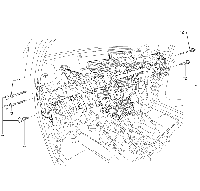
Text in Illustration *1 Instrument panel safety pad cap *2 "TORX" bolt
-
-
REMOVE NO. 1 AIR DUCT SUB-ASSEMBLY
-
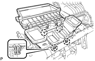
Disengage the 4 claws and remove the No. 1 air duct sub-assembly.
-
-
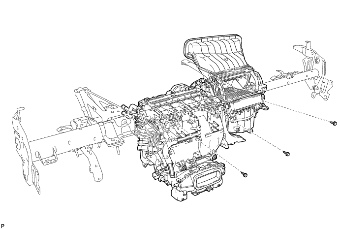
REMOVE AIR CONDITIONING UNIT ASSEMBLY
-
Remove the 3 bolts and air conditioning unit assembly from the instrument panel reinforcement assembly.
-