AIR CONDITIONING SYSTEM Air Conditioning Compressor Magnetic Clutch Circuit
DESCRIPTION
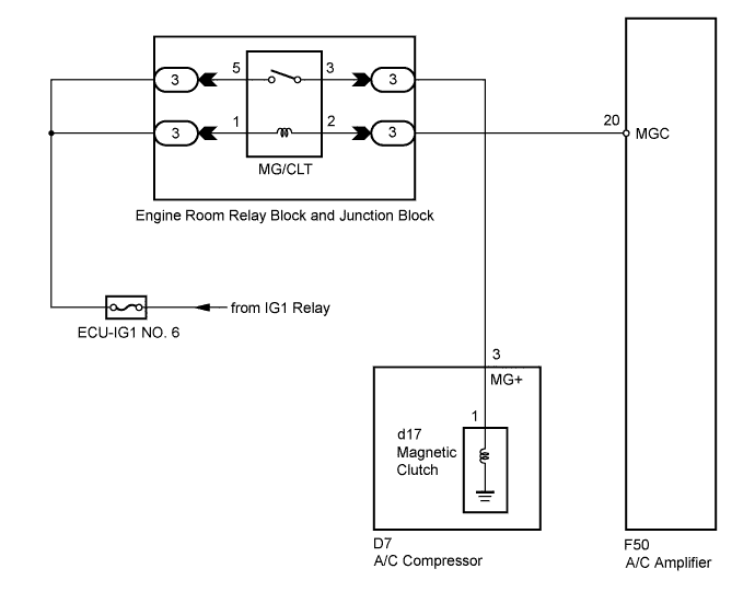
When the A/C amplifier is turned on, a magnetic clutch ON signal is sent from the MGC terminal of the A/C amplifier. Then, the MG/CLT relay turns on to operate the magnetic clutch.
WIRING DIAGRAM
INSPECTION PROCEDURE
Note
Inspect the fuses for circuits related to this system before performing the following inspection procedure.
PROCEDURE
-
CHECK CAN COMMUNICATION SYSTEM
-
Use the intelligent tester to check if the CAN communication system is functioning normally.
Result Result Proceed to CAN DTC is not output A CAN DTC is output B
B 
GO TO CAN COMMUNICATION SYSTEM Click here
A 
-
-
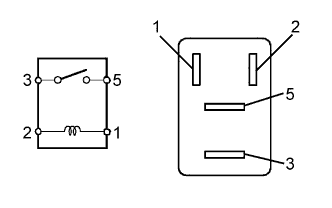
INSPECT RELAY (MG/CLT)
-
Remove the MG/CLT relay from the engine room relay block and junction block.
-
Measure the resistance according to the value(s) in the table below.
Standard Resistance Tester Connection Specified Condition 3 - 5 10 kΩ or higher 3 - 5 Below 1 Ω
(when battery voltage is applied to terminals 1 and 2)
NG
REPLACE RELAY (MG/CLT)
OK
-
-
CHECK HARNESS AND CONNECTOR (ENGINE ROOM RELAY BLOCK AND JUNCTION BLOCK - BATTERY)
-
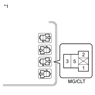
Text in Illustration *1 Component without relay installed
(Engine Room Relay Block and Junction Block)
Remove the MG/CLT relay from the engine room relay block and junction block.
-
Measure the voltage according to the value(s) in the table below.
Standard Voltage Tester Connection Condition Specified Condition Relay block MG/CLT relay terminal 1 - Body ground Engine switch on (IG) 11 to 14 V
NG
REPAIR OR REPLACE HARNESS OR CONNECTOR
OK
-
-
CHECK HARNESS AND CONNECTOR (A/C AMPLIFIER - BATTERY)
-
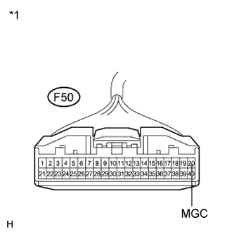
Text in Illustration *1 Front view of wire harness connector
(to A/C Amplifier)
Disconnect the A/C amplifier connector.
-
Measure the voltage according to the value(s) in the table below.
Standard Voltage Tester Connection Condition Specified Condition F50-20 (MGC) - Body ground Engine switch off Below 1 V F50-20 (MGC) - Body ground Engine switch on (IG) 11 to 14 V
NG
REPAIR OR REPLACE HARNESS OR CONNECTOR
OK
-
-
INSPECT A/C AMPLIFIER
-
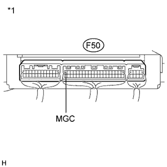
Text in Illustration *1 Component with harness connected
(A/C Amplifier)
Reconnect the A/C amplifier connector.
-
Measure the voltage according to the value(s) in the table below.
Standard Voltage Tester Connection Condition Specified Condition F50-20 (MGC) - Body ground Engine switch on (IG)
A/C switch: off
11 to 14 V F50-20 (MGC) - Body ground Engine switch on (IG)
A/C switch: on
Below 1 V
NG
REPLACE A/C AMPLIFIER Click here
OK
-
-
INSPECT A/C COMPRESSOR
-
Disconnect the A/C compressor connector.
-
Disconnect the magnetic clutch connector.
-
Measure the resistance according to the value(s) in the table below.
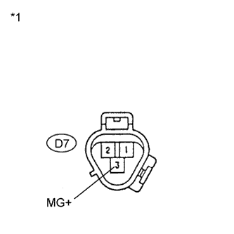
Standard Resistance Tester Connection Condition Specified Condition D7-3 (MG+) - d17-1 Always Below 1 Ω D7-3 (MG+) - Body ground Always 10 kΩ or higher Text in Illustration *1 Component without harness connected
(A/C Compressor)
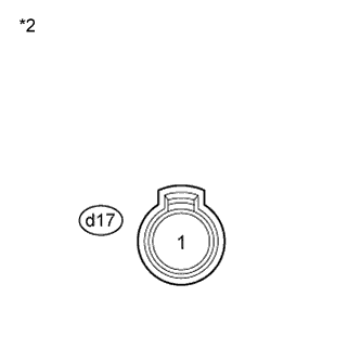
*2 Component without harness connected
(Magnetic Clutch)
NG
REPLACE A/C COMPRESSOR Click here
OK
-
-
INSPECT MAGNETIC CLUTCH
-
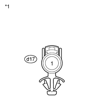
Text in Illustration *1 Component without harness connected
(Magnetic Clutch)
Measure the resistance according to the value(s) in the table below.
Standard Resistance Tester Connection Condition Specified Condition d17-1 - Body ground 20°C (68°F) 3.8 to 4.2 Ω -
When connector terminal d17-1 is connected to a positive (+) battery terminal, check that the following occurs: 1) the magnetic clutch operating sound can be heard, and 2) the magnetic clutch hub and rotor lock.
NG
REPLACE MAGNETIC CLUTCH Click here
OK
-
-
CHECK HARNESS AND CONNECTOR (ENGINE ROOM RELAY BLOCK AND JUNCTION BLOCK - BATTERY)
-
Text in Illustration *1 Component without relay installed
(Engine Room Relay Block and Junction Block
Remove the MG/CLT relay from the engine room relay block and junction block.
-
Measure the voltage according to the value(s) in the table below.
Standard Voltage Tester Connection Condition Specified Condition Relay block MG/CLT relay terminal 5 - Body ground Engine switch on (IG) 11 to 14 V
NG
REPAIR OR REPLACE HARNESS OR CONNECTOR
OK
-
-
CHECK HARNESS AND CONNECTOR (ENGINE ROOM RELAY BLOCK AND JUNCTION BLOCK - A/C COMPRESSOR)
-
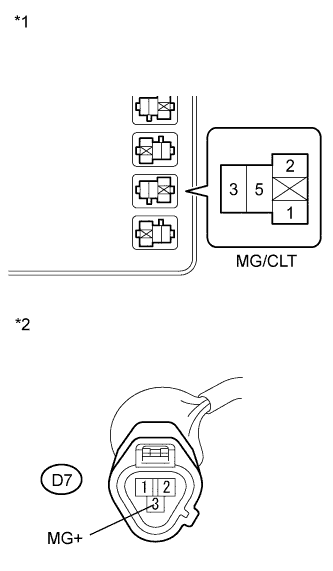
Text in Illustration *1 Component without relay installed
(Engine Room Relay Block and Junction Block)
*2 Front view of wire harness connector
(to A/C Compressor)
Measure the resistance according to the value(s) in the table below.
Standard Resistance Tester Connection Condition Specified Condition Relay block MG/CLT relay terminal 3 - D7-3 (MG+) Always Below 1 Ω D7-3 (MG+) - Body ground Always 10 kΩ or higher Result Result Proceed to NG A OK (When troubleshooting according to Problem Symptoms Table) B OK (When troubleshooting according to the DTC) C
B
PROCEED TO NEXT SUSPECTED AREA SHOWN IN PROBLEM SYMPTOMS TABLE Click here
C
REPLACE A/C AMPLIFIER Click here
A 
REPAIR OR REPLACE HARNESS OR CONNECTOR
-