AIR CONDITIONING SYSTEM, Diagnostic DTC:B1451/51

| DTC Code | DTC Name |
|---|---|
| B1451/51 | Compressor Solenoid Circuit |
DESCRIPTION
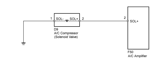
In this circuit, the A/C compressor receives a refrigerant compression demand signal from the A/C amplifier.
Based on this signal, the A/C compressor changes the amount of compressor output.
| DTC No. | DTC Detection Condition | Trouble Area |
|---|---|---|
| B1451/51 | Open or short in A/C compressor solenoid circuit |
|
WIRING DIAGRAM
INSPECTION PROCEDURE
PROCEDURE
-
INSPECT A/C COMPRESSOR (SOLENOID VALVE)
-
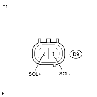
Text in Illustration *1 Component without harness connected
(A/C Compressor (Solenoid Valve))
Disconnect the A/C compressor (solenoid valve) connector.
-
Measure the resistance according to the value(s) in the table below.
Standard Resistance Tester Connection Condition Specified Condition D9-2 (SOL+) - D9-1 (SOL-) 20°C (68°F) 10 to 11 Ω Result Result Proceed to OK A NG (for 2GR-FE) B NG (for 1AR-FE) C
B 
REPLACE A/C COMPRESSOR (SOLENOID VALVE) Click here
C
REPLACE A/C COMPRESSOR (SOLENOID VALVE) Click here
A 
-
-
CHECK HARNESS AND CONNECTOR (A/C COMPRESSOR (SOLENOID VALVE) - BODY GROUND)
-
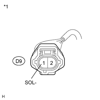
Text in Illustration *1 Front view of wire harness connector
(to A/C Compressor (Solenoid Valve))
Measure the resistance according to the value(s) in the table below.
Standard Resistance Tester Connection Condition Specified Condition D9-1 (SOL-) - Body ground Always Below 1 Ω
NG
REPAIR OR REPLACE HARNESS OR CONNECTOR
OK
-
-
CHECK HARNESS AND CONNECTOR (A/C COMPRESSOR (SOLENOID VALVE) - A/C AMPLIFIER)
-
Disconnect the A/C amplifier connector.
-
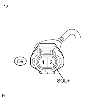
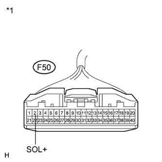
Text in Illustration *1 Front view of wire harness connector
(to A/C Amplifier)
*2 Front view of wire harness connector
(to A/C Compressor (Solenoid Valve))
Measure the resistance according to the value(s) in the table below.
Standard Resistance Tester Connection Condition Specified Condition F50-2 (SOL+) - D9-2 (SOL+) Always Below 1 Ω F50-2 (SOL+) - Body ground Always 10 kΩ or higher Result Result Proceed to NG A OK (When troubleshooting according to Problem Symptoms Table) B OK (When troubleshooting according to the DTC) C
B
PROCEED TO NEXT SUSPECTED AREA SHOWN IN PROBLEM SYMPTOMS TABLE Click here
C
REPLACE A/C AMPLIFIER Click here
A 
REPAIR OR REPLACE HARNESS OR CONNECTOR
-