AIR CONDITIONING SYSTEM, Diagnostic DTC:B1422/22

| DTC Code | DTC Name |
|---|---|
| B1422/22 | Compressor Lock Sensor Circuit |
SYSTEM DESCRIPTION
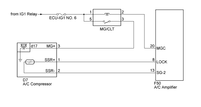
The ECM sends the engine speed signal to the A/C amplifier via CAN communication.
The A/C amplifier reads the difference between compressor speed and engine speed. When the difference becomes too large, the A/C amplifier determines that the compressor is locked, and turns the magnetic clutch off.
| DTC No. | DTC Detection Condition | Trouble Area |
|---|---|---|
| B1422/22 | Open or short in compressor lock sensor circuit |
|
WIRING DIAGRAM
INSPECTION PROCEDURE
PROCEDURE
-
CHECK CAN COMMUNICATION SYSTEM
-
Use the intelligent tester to check if the CAN communication system is functioning normally.
Result Result Proceed to CAN DTC is not output A CAN DTC is output B
B 
GO TO CAN COMMUNICATION SYSTEM Click here
A 
-
-
PERFORM ACTIVE TEST USING INTELLIGENT TESTER
-
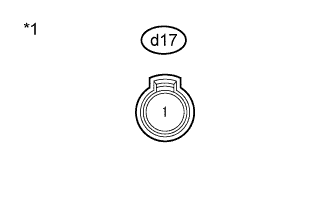
Text in Illustration *1 Front view of wire harness connector
(to Magnetic Clutch)
Disconnect the magnetic clutch connector.
-
Install SST to the connector on the magnetic clutch relay side.
- SST
- 09843-18040
-
Connect the intelligent tester to the DLC3.
-
Start the engine.
-
Turn the intelligent tester on.
-
Enter the following menus: Body / Air Conditioner / Active Test.
-
Measure the voltage according to the value(s) in the table below.
Note
Take care that the connector or measurement tools do not contact the rotating parts of the engine
Air Conditioner Tester Display Test Part Control Range Diagnostic Note Magnetic Clutch Relay A/C compressor OFF, ON - Standard Voltage Tester Connection Condition Specified Condition d17 - Body ground
-
Engine is running
-
Active Test above is being performed
11 to 14 V Tech Tips
When performing the Active Test, voltage between 11 and 14 V is output for approximately 3 seconds.
-
-
Reconnect the magnetic clutch connector.
NG
GO TO AIR CONDITIONING COMPRESSOR MAGNETIC CLUTCH CIRCUIT Click here
OK
-
-
INSPECT MAGNETIC CLUTCH
-
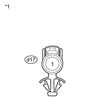
Text in Illustration *1 Component without harness connected
(Magnetic Clutch)
Measure the resistance according to the value(s) in the table below.
Standard Resistance Tester Connection Condition Specified Condition d17-1 - Body ground 20°C (68°F) 3.8 to 4.2 Ω -
When connector terminal d17-1 is connected to a positive (+) battery terminal, check that the following occurs: 1) the magnetic clutch operating sound can be heard, and 2) the magnetic clutch hub and rotor lock.
NG
REPLACE MAGNETIC CLUTCH Click here
OK
-
-
INSPECT A/C COMPRESSOR (A/C LOCK SENSOR)
-
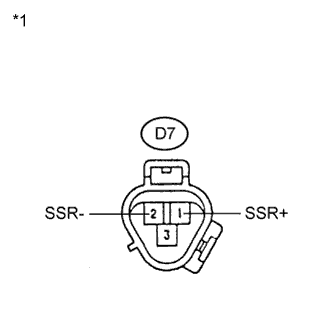
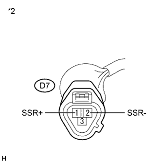
Text in Illustration *1 Component without harness connected
(A/C Compressor)
Disconnect the A/C compressor connector.
-
Measure the resistance according to the value(s) in the table below.
Standard Resistance Tester Connection Condition Specified Condition D7-1 (SSR+) - D7-2 (SSR-) 20°C (68°F) 160 to 320 Ω
NG
REPLACE A/C COMPRESSOR (A/C LOCK SENSOR) Click here
OK
-
-
CHECK HARNESS AND CONNECTOR (A/C AMPLIFIER - A/C LOCK SENSOR)
-
Disconnect the A/C amplifier connector.
-
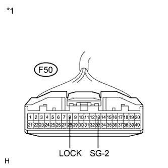
Text in Illustration *1 Front view of wire harness connector
(to A/C Amplifier)
*2 Front view of wire harness connector
(to A/C Compressor)
Measure the resistance according to the value(s) in the table below.
Standard Resistance Tester Connection Condition Specified Condition F50-8 (LOCK) - D7-1 (SSR+) Always Below 1 Ω F50-13 (SG-2) - D7-2 (SSR-) Always Below 1 Ω F50-8 (LOCK) - Body ground Always 10 kΩ or higher F50-13 (SG-2) - Body ground Always 10 kΩ or higher Result Result Proceed to NG A OK (When troubleshooting according to Problem Symptoms Table) B OK (When troubleshooting according to the DTC) C
B
PROCEED TO NEXT SUSPECTED AREA SHOWN IN PROBLEM SYMPTOMS TABLE Click here
C
REPLACE A/C AMPLIFIER Click here
A 
REPAIR OR REPLACE HARNESS OR CONNECTOR
-