SEAT BELT WARNING SYSTEM Front Passenger Side Seat Belt Warning Light Malfunction
DESCRIPTION
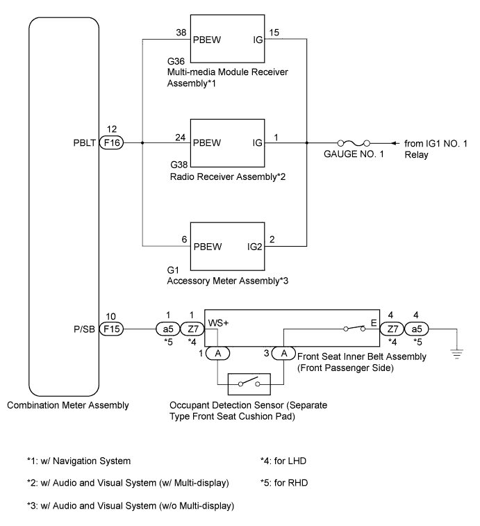
When the front passenger side seat belt is not fastened with the engine switch on (IG) and the front passenger side seat occupied, the front passenger side seat belt warning light on the multi-media module receiver assembly*1, radio receiver assembly*2 or accessory meter assembly*3 blinks. The occupant detection sensor detects if the front passenger side seat is occupied and sends signals to the combination meter assembly. The front seat inner belt assembly detects the front passenger side seat belt condition and sends signals to the combination meter assembly. After receiving the signals from the occupant detection sensor and front seat inner belt assembly, the combination meter illuminates the front passenger side seat belt warning light on the multi-media module receiver assembly*1, radio receiver assembly*2 or accessory meter assembly*3.
-
*1: w/ Navigation System
-
*2: w/ Audio and Visual System (w/ Multi-display)
-
*3: w/ Audio and Visual System (w/o Multi-display)
WIRING DIAGRAM
INSPECTION PROCEDURE
PROCEDURE
-
READ VALUE USING INTELLIGENT TESTER
-
Connect the intelligent tester to the DLC3.
-
Turn the engine switch on (IG).
-
Turn the intelligent tester on.
-
Enter the following menus: Body / Combination Meter / Data List.
-
Read the Data List according to the display on the intelligent tester.
Combination Meter (Combination Meter Assembly) Tester Display Measurement Item/Range Normal Condition Diagnostic Note P-Seatbelt Buckle SW Front passenger side seat belt buckle switch signal/OFF or ON OFF: Front passenger side seat belt fastened with the front passenger side seat occupied or the front passenger side seat not occupied.
ON: Front passenger side seat belt not fastened with the front passenger side seat occupied.
- OK ON or OFF appears on the tester screen according to the front passenger side seat belt condition.
NG 
CHECK HARNESS AND CONNECTOR (FRONT PASSENGER SIDE SEAT INNER BELT - COMBINATION METER) Click here
OK 
-
-
PERFORM ACTIVE TEST USING INTELLIGENT TESTER
-
Connect the intelligent tester to the DLC3.
-
Turn the engine switch on (IG).
-
Turn the intelligent tester on.
-
Enter the following menus: Body / Combination Meter / Data List.
-
Perform the Active Test according to the display on the intelligent tester.
Combination Meter (Combination Meter Assembly) Tester Display Test Part Control Range Diagnostic Note Front Passenger Side Seat Belt Front passenger side seat belt warning light OFF or ON Confirm that the vehicle is stopped with the engine idling. OK The front passenger side seat belt warning light on the air conditioning control assembly operates normally.
NG
SYSTEM CHECK Click here
OK 
REPLACE COMBINATION METER ASSEMBLY Click here
-
-
CHECK HARNESS AND CONNECTOR (FRONT PASSENGER SIDE SEAT INNER BELT - COMBINATION METER)
-
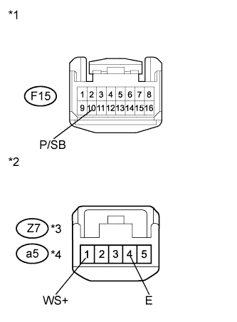
Text in Illustration *1 Front view of wire harness connector
(to Combination Meter Assembly)
*2 Front view of wire harness connector
(to Front Seat Inner Belt Assembly (Front Passenger Side))
*3 for LHD *4 for RHD Disconnect the F15 meter connector.
-
Disconnect the Z7*3 or a5*4 belt connector.
-
*3: for LHD
-
*4: for RHD
-
-
Measure the resistance according to the value(s) in the table below.
Standard Resistance Tester Connection Condition Specified Condition F15-10 (P/SB) - Z7-1 (WS+)*3
F15-10 (P/SB) - a5-1 (WS+)*4
Always Below 1 Ω F15-10 (P/SB) - Body ground Always 10 kΩ or higher Z7-4 (E) - Body ground*3
a5-4 (E) - Body ground*4
Always Below 1 Ω
-
*3: for LHD
-
*4: for RHD
-
NG 
REPAIR OR REPLACE HARNESS OR CONNECTOR
OK
-
-
INSPECT OCCUPANT DETECTION SENSOR (SEPARATE TYPE FRONT SEAT CUSHION PAD)
-
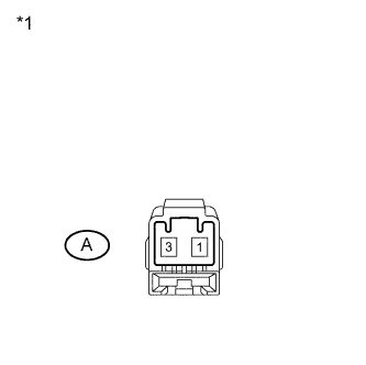
Text in Illustration *1 Component without harness connected
(Occupant Detection Sensor (Separate Type Front Seat Cushion Pad))
Remove the occupant detection sensor (separate type front seat cushion pad) Click here.
-
Measure the resistance according to the value(s) in the table below.
Standard Resistance Tester Connection Condition Specified Condition A-1 - A-3 Front passenger side seat occupied Below 100 Ω A-1 - A-3 Front passenger side seat not occupied 1 MΩ or higher
NG
REPLACE OCCUPANT DETECTION SENSOR (SEPARATE TYPE FRONT SEAT CUSHION PAD) Click here
OK
-
-
INSPECT FRONT SEAT INNER BELT ASSEMBLY (FRONT PASSENGER SIDE)
-
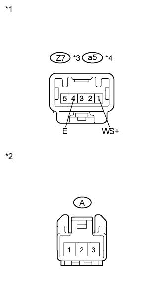
Text in Illustration *1 Component without harness connected
(Front Seat Inner Belt Assembly (Front Passenger Side))
*2 Front view of wire harness connector
(to Occupant Detection Sensor (Separate Type Front Seat Cushion Pad))
*3 for LHD *4 for RHD Remove the front seat inner belt assembly (front passenger side) Click here.
-
Measure the resistance according to the value(s) in the table below.
Standard Resistance Tester Connection Condition Specified Condition Z7-1 (WS+) - A-1*3
a5-1 (WS+) - A-1*4
Always Below 1 Ω Z7-4 (E) - A-3*3
a5-4 (E) - A-3*4
Front passenger side seat belt unfastened Below 1 Ω Z7-4 (E) - A-3*3
a5-4 (E) - A-3*4
Front passenger side seat belt fastened 10 kΩ or higher
-
*3: for LHD
-
*4: for RHD
-
NG
REPLACE FRONT SEAT INNER BELT ASSEMBLY LH Click here
OK
REPLACE COMBINATION METER ASSEMBLY Click here
-
-
SYSTEM CHECK
-
Check the vehicle specification.
Result Result Proceed to w/ Navigation System A w/ Audio and Visual System (w/ Multi-display) B w/ Audio and Visual System (w/o Multi-display) C
B
CHECK HARNESS AND CONNECTOR (RADIO RECEIVER ASSEMBLY - BATTERY) Click here
C
CHECK HARNESS AND CONNECTOR (ACCESSORY METER ASSEMBLY - BATTERY) Click here
A
-
-
CHECK HARNESS AND CONNECTOR (MULTI-MEDIA MODULE RECEIVER ASSEMBLY - BATTERY)
-
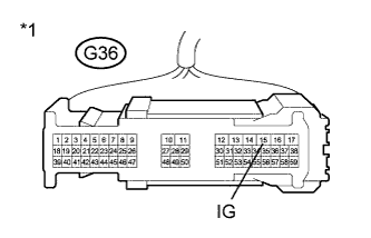
Text in Illustration *1 Front view of wire harness connector
(to Multi-media Module Receiver Assembly)
Disconnect the G36 connector.
-
Measure the voltage according to the value(s) in the table below.
Standard Voltage Tester Connection Condition Specified Condition G36-15 (IG) - Body ground Engine switch on (IG) 11 to 14 V G36-15 (IG) - Body ground Engine switch off Below 1 V
NG
REPAIR OR REPLACE HARNESS OR CONNECTOR
OK
-
-
CHECK HARNESS AND CONNECTOR (COMBINATION METER ASSEMBLY - MULTI-MEDIA MODULE RECEIVER ASSEMBLY)
-
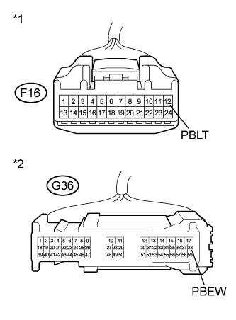
Text in Illustration *1 Front view of wire harness connector
(to Combination Meter Assembly)
*2 Front view of wire harness connector
(to Multi-media Module Receiver Assembly)
Disconnect the F16 meter connector.
-
Measure the resistance according to the value(s) in the table below.
Standard Resistance Tester Connection Condition Specified Condition F16-12 (PBLT) - G36-38 (PBEW) Always Below 1 Ω F16-12 (PBLT) - Body ground Always 10 kΩ or higher
NG
REPAIR OR REPLACE HARNESS OR CONNECTOR
OK
-
-
CHECK HARNESS AND CONNECTOR (COMBINATION METER ASSEMBLY - BATTERY)
-
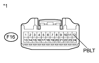
Text in Illustration *1 Front view of wire harness connector
(to Combination Meter Assembly)
Reconnect the G36 connector.
-
Measure the voltage according to the value(s) in the table below.
Standard Voltage Tester Connection Condition Specified Condition F16-12 (PBLT) - Body ground Engine switch on (IG) 11 to 14 V F16-12 (PBLT) - Body ground Engine switch off Below 1 V
NG
REPLACE MULTI-MEDIA MODULE RECEIVER ASSEMBLY Click here
OK
REPLACE COMBINATION METER ASSEMBLY Click here
-
-
CHECK HARNESS AND CONNECTOR (RADIO RECEIVER ASSEMBLY - BATTERY)
-
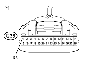
Text in Illustration *1 Front view of wire harness connector
(to Radio Receiver Assembly)
Disconnect the G38 connector.
-
Measure the voltage according to the value(s) in the table below.
Standard Voltage Tester Connection Condition Specified Condition G38-1 (IG) - Body ground Engine switch on (IG) 11 to 14 V G38-1 (IG) - Body ground Engine switch off Below 1 V
NG
REPAIR OR REPLACE HARNESS OR CONNECTOR
OK
-
-
CHECK HARNESS AND CONNECTOR (COMBINATION METER ASSEMBLY - RADIO RECEIVER ASSEMBLY)
-
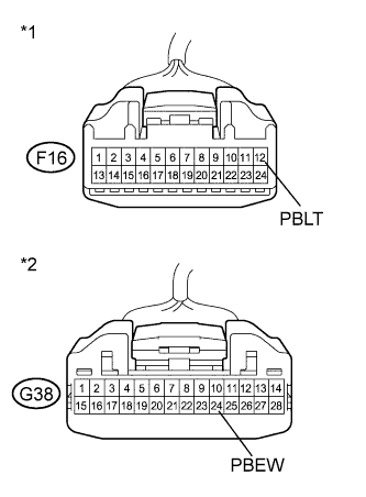
Text in Illustration *1 Front view of wire harness connector
(to Combination Meter Assembly)
*2 Front view of wire harness connector
(to Radio Receiver Assembly)
Disconnect the F16 meter connector.
-
Measure the resistance according to the value(s) in the table below.
Standard Resistance Tester Connection Condition Specified Condition F16-12 (PBLT) - G38-24 (PBEW) Always Below 1 Ω F16-12 (PBLT) - Body ground Always 10 kΩ or higher
NG
REPAIR OR REPLACE HARNESS OR CONNECTOR
OK
-
-
CHECK HARNESS AND CONNECTOR (COMBINATION METER ASSEMBLY - BATTERY)
-
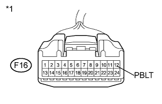
Text in Illustration *1 Front view of wire harness connector
(to Combination Meter Assembly)
Reconnect the G38 connector.
-
Measure the voltage according to the value(s) in the table below.
Standard Voltage Tester Connection Condition Specified Condition F16-12 (PBLT) - Body ground Engine switch on (IG) 11 to 14 V F16-12 (PBLT) - Body ground Engine switch off Below 1 V
NG
REPLACE RADIO RECEIVER ASSEMBLY Click here
OK
REPLACE COMBINATION METER ASSEMBLY Click here
-
-
CHECK HARNESS AND CONNECTOR (ACCESSORY METER ASSEMBLY - BATTERY)
-
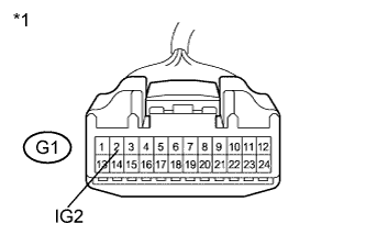
Text in Illustration *1 Front view of wire harness connector
(to Accessory Meter Assembly)
Disconnect the G1 connector.
-
Measure the voltage according to the value(s) in the table below.
Standard Voltage Tester Connection Condition Specified Condition G1-2 (IG2) - Body ground Engine switch on (IG) 11 to 14 V G1-2 (IG2) - Body ground Engine switch off Below 1 V
NG
REPAIR OR REPLACE HARNESS OR CONNECTOR
OK
-
-
CHECK HARNESS AND CONNECTOR (COMBINATION METER ASSEMBLY - ACCESSORY METER ASSEMBLY)
-
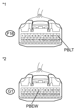
Text in Illustration *1 Front view of wire harness connector
(to Combination Meter Assembly)
*2 Front view of wire harness connector
(to Accessory Meter Assembly)
Disconnect the F16 connector.
-
Measure the resistance according to the value(s) in the table below.
Standard Resistance Tester Connection Condition Specified Condition F16-12 (PBLT) - G1-6 (PBEW) Always Below 1 Ω G1-6 (PBEW) - Body ground Always 10 kΩ or higher
NG
REPAIR OR REPLACE HARNESS OR CONNECTOR
OK
-
-
CHECK HARNESS AND CONNECTOR (COMBINATION METER ASSEMBLY - BATTERY)
-
Text in Illustration *1 Front view of wire harness connector
(to Combination Meter Assembly)
Disconnect the G1 connector.
-
Measure the voltage according to the value(s) in the table below.
Standard Voltage Tester Connection Condition Specified Condition F16-12 (PBLT) - Body ground Engine switch on (IG) 11 to 14 V F16-12 (PBLT) - Body ground Engine switch off Below 1 V
NG
REPLACE ACCESSORY METER ASSEMBLY Click here
OK
REPLACE COMBINATION METER ASSEMBLY Click here
-