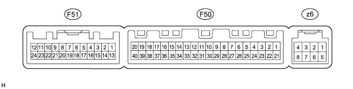
AIR CONDITIONING SYSTEM TERMINALS OF ECU

-
A/C AMPLIFIER
Tech Tips
Check from the rear of the connector while it is connected to the A/C amplifier.
Terminal No.
(Symbol)
Wiring Color Terminal Description Condition Specified Condition F50-1 (IG+) - F50-14 (GND) P - W-B Power source (IG) Engine switch on (IG) 11 to 14 V F50-1 (IG+) - F50-14 (GND) P - W-B Power source (IG) Engine switch off Below 1 V F50-2 (SOL+) - F50-14 (GND) SB - W-B A/C compressor solenoid operation signal Engine running
A/C switch: on
Blower switch: LO
Pulse generation
(See waveform 1)
F50-5 (TAM) - F50-13 (SG-2) V - LG Ambient temperature sensor signal Engine switch on (IG)
Ambient temperature: 25°C (77°F)
1.35 to 1.75 V F50-5 (TAM) - F50-13 (SG-2) V - LG Ambient temperature sensor signal Engine switch on (IG)
Ambient temperature: 40°C (104°F)
0.9 to 1.2 V F50-6 (DGS) - F50-13 (SG-2)*1 SB - LG Smog ventilation sensor signal (HC, CO) After 30 seconds from engine switch on (IG) and sensor exposed to exhaust gas (HC, CO) 1.0 to 4.5 V F50-7 (FLOQ) - F50-13 (SG-2) Y - LG A/C flow sensor signal Engine switch on (IG)
A/C switch: off
3.8 to 4.2 V F50-7 (FLOQ) - F50-13 (SG-2) Y - LG A/C flow sensor signal Engine switch on (IG)
A/C switch: on
Blower switch: HI
0.7 to 3.8 V F50-8 (LOCK) - F50-13 (SG-2)*4 LG - LG A/C compressor lock sensor signal Engine running
Blower switch: LO
A/C switch: on
Pulse generation
(See waveform 2)
F50-9 (PRE) - F50-13 (SG-2) W - LG A/C pressure sensor signal Start engine, Operate A/C system, Refrigerant pressure: Abnormal pressure (more than 3140 kPa (32.0 kgf/cm2, 455 psi))
4.84 V or higher F50-9 (PRE) - F50-13 (SG-2) W - LG A/C pressure sensor signal Start engine, Operate A/C system, Refrigerant pressure: Abnormal pressure (less than 196 kPa (2.0 kgf/cm2, 28 psi))
Below 0.73 V F50-9 (PRE) - F50-13 (SG-2) W - LG A/C pressure sensor signal Start engine, Operate A/C system, Refrigerant pressure: Normal pressure (less than 3140 kPa (32.0 kgf/cm2, 455 psi) and more than 196 kPa (2.0 kgf/cm2, 28 psi))
0.73 to 4.84 V F50-10 (S5-3) - F50-13 (SG-2) P - LG Power supply for A/C pressure sensor Engine switch on (IG) 4.75 to 5.25 V F50-10 (S5-3) - F50-13 (SG-2) P - LG Power supply for A/C pressure sensor Engine switch off Below 1 V F50-11 (CANH) - F50-12 (CANL) B - W CAN communication system CAN communication circuit Pulse generation F50-13 (SG-2) - Body ground LG - Body ground Ground for A/C pressure sensor, A/C ambient temperature sensor, A/C lock sensor, smog ventilation sensor, A/C mass flow sensor Always Below 1 V F50-14 (GND) - Body ground W-B - Body ground Ground for main power supply Always Below 1 V F50-20 (MGC) - F50-14 (GND)*4 BE - W-B A/C compressor magnetic clutch operation signal Engine switch on (IG)
Blower switch: LO
A/C switch: off
11 to 14 V F50-20 (MGC) - F50-14 (GND)*4 BE - W-B A/C compressor magnetic clutch operation signal Engine switch on (IG)
Blower switch: LO
A/C switch: on
Below 1 V F50-21 (B) - F50-14 (GND) G - W-B Power source (Back-up) Always 11 to 14 V F50-23 (BLW) - F50-14 (GND) L - W-B Blower motor speed control signal Engine switch on (IG)
Blower switch: LO
Pulse generation
(See waveform 3)
F50-29 (TR) - F50-34 (SG-1) BE - V Room temperature sensor signal Engine switch on (IG)
Cabin temperature: 25°C (77°F)
1.8 to 2.2 V F50-29 (TR) - F50-34 (SG-1) BE - V Room temperature sensor signal Engine switch on (IG)
Cabin temperature: 40°C (104°F)
1.2 to 1.6 V F50-30 (S5-1) - F50-13 (SG-2) BR - LG Power supply for A/C flow sensor Engine switch off Below 1 V F50-30 (S5-1) - F50-13 (SG-2) BR - LG Power supply for A/C flow sensor Engine switch on (IG) 4.5 to 5.5 V F50-32 (TSP) - F50-14 (GND) Y - W-B*2
R - W-B*3
Solar sensor signal (for Front passenger side) Engine switch on (IG)
Solar sensor subjected to electric light
0.8 to 4.3 V F50-32 (TSP) - F50-14 (GND) Y - W-B*2
R - W-B*3
Solar sensor signal (for Front passenger side) Engine switch on (IG)
Solar sensor covered with a cloth
Below 0.8 V F50-33 (TSD) - F50-14 (GND) R - W-B*2
Y - W-B*3
Solar sensor signal (for Driver side) Engine switch on (IG)
Solar sensor subjected to electric light
0.8 to 4.3 V F50-33 (TSD) - F50-14 (GND) R - W-B*2
Y - W-B*3
Solar sensor signal (for Driver side) Engine switch on (IG)
Solar sensor covered with a cloth
Below 0.8 V F50-34 (SG-1) - Body ground V - Body ground Ground for room temperature sensor Always Below 1 V F50-37 (LIN1) - F50-14 (GND)*5 SB - W-B LIN communication signal Engine switch on (IG) Pulse generation F51-3 (DGS1) - F50-14 (GND)*1 B - W-B Smog ventilation sensor signal (NOx) After 30 seconds from engine switch on (IG) and sensor exposed to exhaust gas (NOx) 1.0 to 4.5 V z6-2 (BUSG) - Body ground - Ground for BUS IC Always Below 1 V z6-3 (BUS) - z6-2 (BUSG) - BUS IC control signal Engine switch on (IG) Pulse generation z6-4 (BBUS) - z6-2 (BUSG) - Power supply for BUS IC Always 11 to 14 V z6-5 (SG) - Body ground - Ground for evaporator temperature sensor Always Below 1 V z6-6 (TE) - z6-5 (SG) - A/C evaporator temperature sensor signal Engine switch on (IG)
Evaporator temperature: 0°C (32°F)
1.7 to 2.1 V z6-6 (TE) - z6-5 (SG) - A/C evaporator temperature sensor signal Engine switch on (IG)
Evaporator temperature: 15°C (59°F)
0.9 to 1.3 V
-
*1: w/ Smog Ventilation Sensor
-
*2: for LHD
-
*3: for RHD
-
*4: for 2GR-FE
-
*5: w/ Multi-display
-
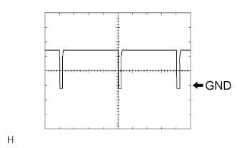
Waveform 1:
Item Content Terminal No. F50-2 (SOL+) - F50-14 (GND) Tool Setting 5 V/DIV., 500 μs/DIV. Vehicle Condition Engine running
A/C switch: on
-
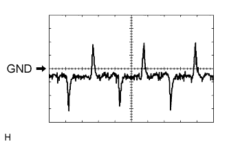
Waveform 2:
Item Content Terminal No. F50-8 (LOCK) - F50-13 (SG-2) Tool Setting 200 mV/DIV., 10 ms./DIV. Vehicle Condition Engine running
Blower switch: LO
A/C switch: on
-
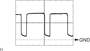
Waveform 3:
Item Content Terminal No. F50-23 (BLW) - F50-14 (GND) Tool Setting 1 V/DIV., 500 μs/DIV. Vehicle Condition Engine switch on (IG)
Blower switch: LO
-
-
MULTI-MEDIA MODULE RECEIVER ASSEMBLY (A/C CONTROL PANEL) (w/ Navigation System) Click here
-
RADIO RECEIVER ASSEMBLY (A/C CONTROL PANEL) (w/ Audio and Visual System (w/ Multi-display)) Click here
-
RADIO RECEIVER ASSEMBLY (A/C CONTROL PANEL) (w/ Audio and Visual System (w/o Multi-display))
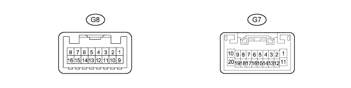
Tech Tips
Check from the rear of the connector while it is connected to the radio receiver assembly (A/C control panel).
Terminal No.
(Symbol)
Wiring Color Terminal Description Condition Specified Condition G7-1 (B) - Body ground V - Body ground Power source (Back-up) Always 11 to 14 V G8-5 (TX+) Y AVC-LAN communication signal - - G8-9 (GND) - Body ground BR - Body ground Ground for radio receiver (A/C control panel) Always Below 1 V G8-13 (TX-) W AVC-LAN communication signal - - G8-16 (ACC) - G8-9 (GND) GR - BR Power source (ACC) Engine switch off Below 1 V G8-16 (ACC) - G8-9 (GND) GR - BR Power source (ACC) Engine switch on (ACC) 11 to 14 V -
ACCESSORY METER ASSEMBLY (w/o Multi-display) Click here
-
MULTI-DISPLAY ASSEMBLY (w/ Navigation System) Click here
-
MULTI-DISPLAY ASSEMBLY (w/ Audio and Visual System (w/ Multi-display)) Click here