PRE-CRASH SAFETY SYSTEM, Diagnostic DTC:U0122, U0123, U0126, U0140, U0151, U0235, U1002, U1100, U1104

| DTC Code | DTC Name |
|---|---|
| U0122 | Lost Communication with Vehicle Dynamics Control Module |
| U0123 | Lost Communication with Yaw Rate Sensor Module |
| U0126 | Lost Communication with Steering Angle Sensor Module |
| U0140 | Lost Communication with Main Body ECU |
| U0151 | Lost Communication with Airbag ECU |
| U0235 | Lost Communication with Cruise Control Front Distance Range Sensor |
| U1002 | Lost Communication with Gateway Module |
| U1100 | Lost Communication with Seat Belt Control ECU |
| U1104 | Lost Communication with Driving Support ECU |
DESCRIPTION
The driving support ECU uses the millimeter wave radar sensor to detect obstacles in front of the vehicle.
Based on this information, the driving support ECU sends pre-crash control operation signals.
These DTCs are stored when a communication malfunction occurs between the sensors and ECUs that detect collisions, or between ECUs that perform the pre-crash control.
| DTC No. | DTC Detection Condition | Trouble Area |
|---|---|---|
| U0122 |
|
|
| U0123 | When the engine switch is on (IG), a communication error between the yaw rate sensor and the driving support ECU is detected for approximately 4 second. |
|
| U0126 | When the engine switch is on (IG), a communication error between the steering sensor and the driving support ECU is detected for approximately 5 second. |
|
| U0140 | While engine switch is on (IG), communication stop between main body ECU and seat belt control ECU continues for 6 second or more. |
|
| U0151 | While engine switch is on (IG), communication stop between center airbag sensor and seat belt control ECU continues for 6 second or more. |
|
| U0235 | When the engine switch is on (IG), a communication error between the millimeter wave radar sensor and the driving support ECU is detected for approximately 2 seconds. |
|
| U1002 | When the engine switch is on (IG), a communication error between the millimeter wave radar sensor and the driving support ECU is detected for approximately 2 seconds. |
|
| U1100 | When the engine switch is on (IG), a communication error between the seat belt control ECU and the driving support ECU is detected for approximately 10 second. |
|
| U1104 |
|
|
WIRING DIAGRAM

INSPECTION PROCEDURE
PROCEDURE
-
CHECK CAN COMMUNICATION SYSTEM
-
Select "CAN Bus Check" from the "System Selection Menu" screen on the intelligent tester.
-
Select "Communication Malfunction DTC" from the "CAN Bus Check" screen, and then select "Enter".
Result Result Proceed to CAN DTC is not output A CAN DTC is output B
B 
GO TO CAN COMMUNICATION SYSTEM Click here
A 
-
-
CHECK CAN COMMUNICATION SYSTEM
-
Select "CAN Bus Check" from the "System Selection Menu" on the intelligent tester.
-
Select "Communication Malfunction Check" from the "CAN Bus Check" screen, and then select "OK".
OK CAN communication is normal.
NG
GO TO CAN COMMUNICATION SYSTEM Click here
OK
-
-
CHECK HARNESS AND CONNECTOR (DRIVING SUPPORT ECU - MILLIMETER WAVE RADAR SENSOR)
-
Disconnect the driving support ECU connector.
-
Disconnect the millimeter wave radar sensor connector.
-
Measure the resistance according to the value(s) in the table below.
Standard Resistance Tester Connection Condition Specified Condition C1-40 (CA1P) - B1-4 (CA1P) Always Below 1 Ω C1-18 (CA1N) - B1-3 (CA1N) Always Below 1 Ω C1-40 (CA1P) or B1-4 (CA1P) - Body ground Always 10 kΩ or higher C1-18 (CA1N) or B1-3 (CA1N) - Body ground Always 10 kΩ or higher -
Reconnect the millimeter wave radar sensor connector.
-
Reconnect the driving support ECU connector.
NG
REPAIR OR REPLACE HARNESS OR CONNECTOR
OK
-
-
CHECK TERMINAL VOLTAGE (POWER SOURCE OF DRIVING SUPPORT ECU)
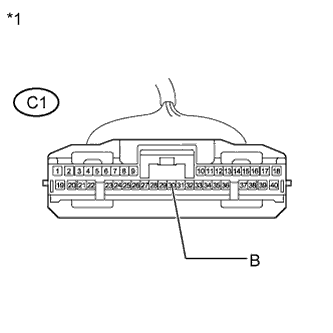
Text in Illustration *1 Front view of wire harness connector
(to Driving Support ECU)
-
Disconnect the driving support ECU connector.
-
Measure the voltage and resistance according to the value(s) in the table below.
Standard Voltage Tester Connection Condition Specified Condition C1-30 (B) - Body ground Engine switch on (IG) 11 to 14 V C1-30 (B) - Body ground Engine switch off Below 1 V -
Reconnect the driving support ECU connector.
NG
REPAIR OR REPLACE HARNESS OR CONNECTOR (DRIVING SUPPORT ECU - BODY GROUND)
OK
-
-
CHECK HARNESS AND CONNECTOR (DRIVING SUPPORT ECU - BODY GROUND)
-
Disconnect the driving support ECU connector.
-
Measure the resistance according to the value(s) in the table below.
Standard Resistance Tester Connection Condition Specified Condition C1-25 (GND) - Body ground Always Below 1 Ω -
Reconnect the driving support ECU connector.
NG
REPAIR OR REPLACE HARNESS OR CONNECTOR (DRIVING SUPPORT ECU - BODY GROUND)
OK
-
-
CHECK TERMINAL VOLTAGE (POWER SOURCE OF MILLIMETER WAVE RADAR SENSOR)
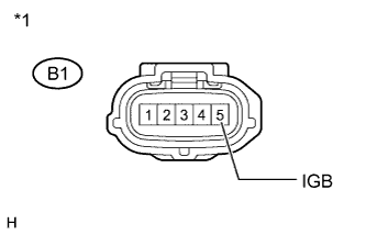
Text in Illustration *1 Front view of wire harness connector
(to Millimeter Wave Radar Sensor)
-
Disconnect the millimeter wave radar sensor connector.
-
Measure the voltage and resistance according to the value(s) in the table below.
Standard Voltage Tester Connection Condition Specified Condition B1-5 (IGB) - Body ground Engine switch on (IG) 11 to 14 V B1-5 (IGB) - Body ground Engine switch off Below 1 V -
Reconnect the millimeter wave radar sensor connector.
NG
REPAIR OR REPLACE HARNESS OR CONNECTOR (MILLIMETER WAVE RADAR SENSOR - BODY GROUND)
OK
-
-
CHECK HARNESS AND CONNECTOR (MILLIMETER WAVE RADAR SENSOR - BODY GROUND)
-
Disconnect the millimeter wave radar sensor connector.
-
Measure the resistance according to the value(s) in the table below.
Standard Resistance Tester Connection Condition Specified Condition B1-2 (SGND) - Body ground Always Below 1 Ω -
Reconnect the millimeter wave radar sensor connector.
NG
REPAIR OR REPLACE HARNESS OR CONNECTOR (MILLIMETER WAVE RADAR SENSOR - BODY GROUND)
OK
-
-
CHECK MILLIMETER WAVE RADAR SENSOR
-
Replace the millimeter wave radar sensor with a new one Click here.
-
Perform millimeter wave radar sensor adjustment Click here.
NEXT
-
-
CHECK DTC OUTPUT
-
Clear the DTCs Click here.
-
Make sure that the DTC detection conditions are met.
Tech Tips
If the detection conditions are not met, the system cannot detect the malfunction.
-
Check for DTCs Click here.
Note
When replacing the driving support ECU, always replace it with a new one. If a driving support ECU which was installed to another vehicle is used, the information stored in the driving support ECU will not match the information from the vehicle. As a result, a DTC may be stored.
Result Result Proceed to DTC U0235 and U1104 are not output A DTC U0235 or U1104 is output B
B
REPLACE DRIVING SUPPORT ECU Click here
A 
END
-