ДАТЧИК ПОЛОЖЕНИЯ РЫЧАГА ПЕРЕКЛЮЧЕНИЯ ПЕРЕДАЧ УСТАНОВКА
-
INSTALL SHIFT LEVER POSITION SENSOR
Tech Tips
Make sure that the manual shaft has not been rotated prior to installing the shift lever position sensor as the detent spring may become detached from the manual shaft.
-
Temporarily install the shift lever position sensor to the hybrid vehicle transmission assembly with the 2 bolts.
Tech Tips
Tighten the bolt to the specified torque when adjusting the shift lever position sensor.
-
Install the lock plate and the lock nut to the shift lever position sensor.
- Torque:
- 6.9 N*m { 70 kgf*cm, 61 in.*lbf }
-
Temporarily install the transmission control shaft lever to the shift lever position sensor with the spring washer and nut.
Tech Tips
Tighten the nut to the specified torque when adjusting the shift lever position sensor.
-
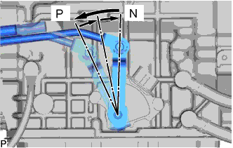
Turn the transmission control shaft lever counterclockwise until it stops, then turn it clockwise 2 notches.
-
Remove the nut, spring washer and transmission control shaft lever from the shift lever position sensor.
-
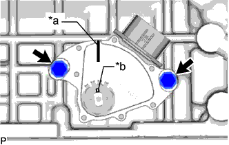
Text in Illustration *a Neutral Basic Line *b Groove Align the neutral basic line with the groove as shown in the illustration.
-
Hold the shift lever position sensor in that position and tighten the 2 bolts.
- Torque:
- 5.4 N*m { 55 kgf*cm, 48 in.*lbf }
-
Using a screwdriver, stake the lock nut with the lock plate.
Note
Check that the lock nut is securely installed.
-
Install the transmission control shaft lever with floor shift gear shifting rod sub-assembly to the shift lever position sensor with the nut and spring washer.
- Torque:
- 16 N*m { 160 kgf*cm, 12 ft.*lbf }
-
Connect the shift lever position sensor connector.
-
-
INSPECT SHIFT LEVER POSITION SENSOR
-
Apply the parking brake.
-
Chock all 4 wheels to secure the vehicle.
-
Turn the power switch on (READY).
-
Move the shift lever to D and release the brake.
Note
Be sure to apply the parking brake and chock all 4 wheels to secure the vehicle.
-
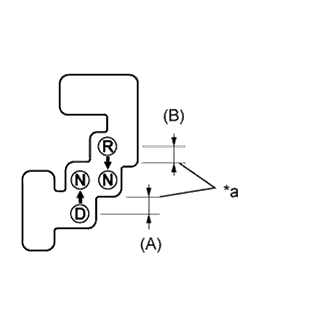
Text in Illustration *a Gear Disengagement Point Slowly move the shift lever to N and measure the moving distance (A) of the shift lever from the original point to the gear disengagement point.
Note
Be sure to move the shift lever slowly.
-
Move the shift lever to R and release the brake.
Note
Be sure to apply the parking brake and chock all 4 wheels to secure the vehicle.
-
Slowly move the shift lever to N and measure the moving distance (B) of the shift lever from the original point to the vehicle disengagement point.
Note
Be sure to move the shift lever slowly.
-
Check that the moving distances (A) and (B) shown in the illustration are almost the same.
Tech Tips
-
If the moving distances (A) and (B) are almost the same, adjustment of the shift lever position is not necessary.
-
If the moving distance (A) is shorter than (B), proceed to step [*1] to perform adjustment of the shift lever position.
-
If the moving distance (B) is shorter than (A), proceed to step [*2] to perform adjustment of the shift lever position.
-
-
-
ADJUST SHIFT LEVER POSITION SENSOR
-
If the moving distance (A) is shorter than (B) [*1]
-
Move the shift lever to N.
-
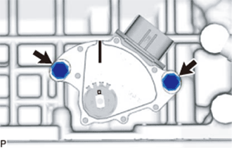
Loosen the 2 bolts.
-
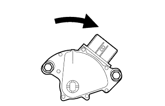
Slightly turn the shift lever position sensor clockwise.
Tech Tips
If the shift lever is moved from D to N, the moving distance of the shift lever from the original point to the gear disengagement point becomes longer.
-
Tighten the 2 bolts.
- Torque:
- 5.4 N*m { 55 kgf*cm, 48 in.*lbf }
-
Recheck the shift lever position sensor position.
-
-
If the moving distance (B) is shorter than (A) [*2]
-
Move the shift lever to N.
-
Loosen the 2 bolts.
-
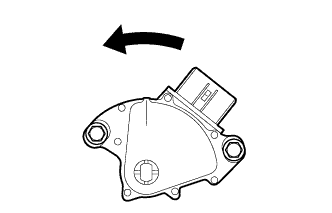
Slightly turn the shift lever position sensor counterclockwise.
Tech Tips
If the shift lever is moved from R to N, the moving distance of the shift lever from the original point to the gear disengagement point becomes longer.
-
Tighten the 2 bolts.
- Torque:
- 5.4 N*m { 55 kgf*cm, 48 in.*lbf }
-
Recheck the shift lever position sensor position.
-
-
-
INSTALL NO. 2 ENGINE UNDER COVER
-
Установите защиту картера двигателя № 2 и закрепите ее 4 винтами и 2 уплотнительными шайбами.
-
-
INSTALL FRONT SUSPENSION MEMBER BRACE
-
Установите скобу элемента передней подвески и закрепите ее фиксатором и 4 болтами.
- Torque:
- 52 Н*м { 53 кгс*см, 38 фунт-сила-футов }
-