ДАТЧИК ПОЛОЖЕНИЯ РЫЧАГА ПЕРЕКЛЮЧЕНИЯ ПЕРЕДАЧ ПРОВЕРКА
-
INSPECT SHIFT LEVER POSITION SENSOR
-
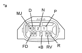
Text in Illustration *a Component without harness connected
(Shift Lever Position Sensor)
Measure the resistance according to the value(s) in the table below when the shift lever is moved to each position.
Standard Resistance Check for Open Tester Connection Condition Specified Condition 7 (+B) - 1 (P) Shift lever in P Below 1 Ω 7 (+B) - 4 (MJ) 7 (+B) - 5 (R) Shift lever in R Below 1 Ω 7 (+B) - 4 (MJ) 7 (+B) - 6 (RV) 7 (+B) - 2 (N) Shift lever in N Below 1 Ω 7 (+B) - 4 (MJ) 7 (+B) - 3 (D) Shift lever in D or S Below 1 Ω 7 (+B) - 9 (FD) 7 (+B) - 4 (MJ) Check for Short Tester Connection Condition Specified Condition 7 (+B) or 1 (P) - Body ground and other terminals Shift lever in P 10 kΩ or higher*1 7 (+B) or 4 (MJ) - Body ground and other terminals 7 (+B) or 5 (R) - Body ground and other terminals Shift lever in R 10 kΩ or higher*1 7 (+B) or 4 (MJ) - Body ground and other terminals 7 (+B) or 6 (RV) - Body ground and other terminals 7 (+B) or 2 (N) - Body ground and other terminals Shift lever in N 10 kΩ or higher 7 (+B) or 4 (MJ) - Body ground and other terminals 7 (+B) or 3 (D) - Body ground and other terminals Shift lever in D or S 10 kΩ or higher*1 7 (+B) or 9 (FD) - Body ground and other terminals 7 (+B) or 4 (MJ) - Body ground and other terminals Note
*1: The resistance between terminals 7 (+B) and 2 (N) should be between 4.2 and 5.2 kΩ.
-