БЛОК ГИБРИДНОЙ ТРАНСМИССИИ ПОВТОРНАЯ СБОРКА

-
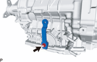
INSTALL OIL STRAINER ASSEMBLY
-
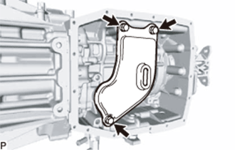
Install a new oil strainer assembly to the hybrid vehicle transmission assembly with the 3 bolts.
- Torque:
- 10 N*m { 102 kgf*cm, 7 ft.*lbf }
-
-
INSTALL OIL COOLER RETURN TUBE
-
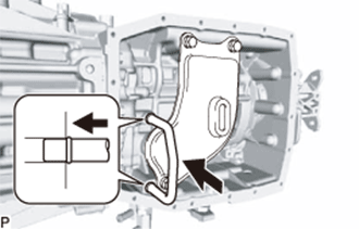
Install the oil cooler return tube to the hybrid vehicle transmission assembly.
-
-
INSTALL TRANSMISSION OIL PAN SUB-ASSEMBLY
-
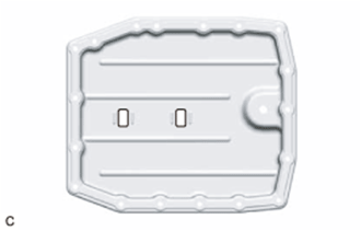
Install the 2 magnets to the transmission oil pan sub-assembly.
-
Install a new gasket to the transmission oil pan sub-assembly.
-
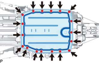
Install the transmission oil pan sub-assembly to the hybrid vehicle transmission assembly with the 18 bolts.
- Torque:
- 7.5 N*m { 76 kgf*cm, 66 in.*lbf }
Tech Tips
Tighten the bolts in diagonal sequence.
-
-
INSTALL TRANSMISSION BREATHER PLUG SUB-ASSEMBLY
-
Using a 14 mm union nut wrench, install the transmission breather plug sub-assembly to the hybrid vehicle transmission assembly.
- Torque:
- 11 N*m { 115 kgf*cm, 8 ft.*lbf }
-
-
INSTALL EXTENSION HOUSING TYPE T OIL SEAL
-
Coat the lip of a new extension housing type T oil seal with a small amount of MP grease.
-
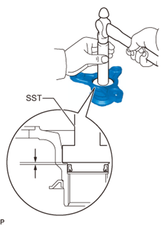
Using SST and a hammer, install the extension housing type T oil seal to the hybrid vehicle transmission assembly.
- SST
- 09308-14010
- 09309-14030
Oil Seal Installation Depth 4.3 to 4.7 mm (0.170 to 0.185 in.)
-
-
INSTALL FLANGE YOKE ASSEMBLY
-
Using SST and a hammer, install a new flange yoke type V oil seal to the flange yoke assembly.
- SST
- 09308-14030
Oil Seal Installation Depth 0 to 0.3 mm (0 to 0.0118 in.) -
Temporarily install the flange yoke assembly to the output shaft with a new lock nut.
-
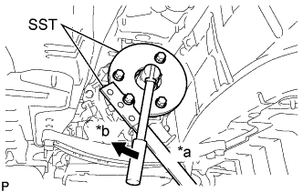
Text in Illustration *a Hold *b Turn Using SST, secure the flange yoke assembly.
- SST
- 09308-14030
- 09330-00021
- 09950-30012 ( 09955-03040 )
-
Using a 30 mm deep socket wrench, tighten the lock nut.
- Torque:
- 126 N*m { 1280 kgf*cm, 93 ft.*lbf }
-
Using a chisel and hammer, stake the lock nut.
-
-
INSTALL HYBRID VEHICLE TRANSMISSION ASSEMBLY TYPE T OIL SEAL
-
Coat the lip of a new hybrid vehicle transmission assembly type T oil seal with MP grease.
-
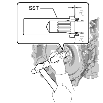
Using SST and a hammer, install the hybrid vehicle transmission assembly type T oil seal to the hybrid vehicle transmission assembly.
- SST
- 09388-40010
Oil Seal Installation Depth 1.0 to 1.8 mm (0.0394 to 0.0708 in.) Note
-
Keep the hybrid vehicle transmission assembly type T oil seal lip free of foreign matter.
-
Do not install the hybrid vehicle transmission assembly type T oil seal at an angle.
-
When installing the hybrid vehicle transmission assembly type T oil seal to the input shaft assembly, do not damage the type T oil seal.
-
-
INSTALL ELBOW
-
Coat 2 new O-ring with ATF and install them to the 2 elbows.
-
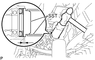
Using SST, install the 2 elbows to the hybrid vehicle transmission assembly so that they are positioned as shown in the illustration.
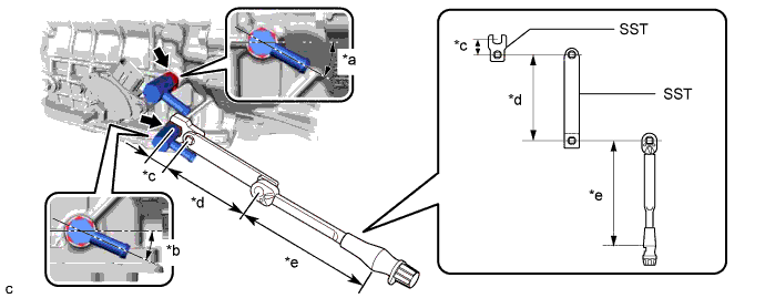
Text in Illustration *a 27 to 31° *b 22 to 26 ° *c Length of SST (Nozzle Retaining Nut Wrench) 34.5 mm *d Length of SST (Torque Wrench Adaptor) 200 mm *e Length of Torque Wrench 180 mm - - - SST
- 09268-78010
- 09961-01270
- Torque:
- without SST
- 36 N*m { 365 kgf*cm, 26 ft.*lbf }
- with SST
- 16 N*m { 158 kgf*cm, 11 ft.*lbf }
Tech Tips
-
This torque value is effective when SST is parallel to the torque wrench.
-
The "with SST" torque value is effective when using SST (Nozzle Retaining Nut Wrench) with a fulcrum length of 34.5 mm (1.36 in.).
-
The "with SST" torque value is effective when using SST (Torque Wrench Adaptor) with a fulcrum length of 200 mm (7.87 in.).
-
The "with SST" torque value is effective when using a torque wrench with a fulcrum length of 180 mm (7.09 in.).
-
If using a torque wrench with a different length, or connecting the torque wrench and SST at an angle, refer to the alternate torque values.
-
-
INSTALL SHIFT LEVER POSITION SENSOR
Tech Tips
Make sure that the manual shaft has not been rotated prior to installing the shift lever position sensor as the detent spring may become detached from the manual shaft.
-
Temporarily install the shift lever position sensor to the hybrid vehicle transmission assembly with the 2 bolts.
Tech Tips
Tighten the bolt to the specified torque when adjusting the shift lever position sensor.
-
Install the lock plate and the lock nut to the shift lever position sensor.
- Torque:
- 6.9 N*m { 70 kgf*cm, 61 in.*lbf }
-
Temporarily install the transmission control shaft lever to the shift lever position sensor with the spring washer and nut.
Tech Tips
Tighten the nut to the specified torque when adjusting the shift lever position sensor.
-
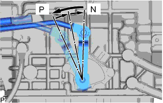
Turn the transmission control shaft lever counterclockwise until it stops, then turn it clockwise 2 notches.
-
Remove the nut, spring washer and transmission control shaft lever from the shift lever position sensor.
-
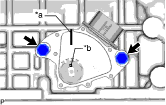
Text in Illustration *a Neutral Basic Line *b Groove Align the neutral basic line with the groove as shown in the illustration.
-
Hold the shift lever position sensor in that position and tighten the 2 bolts.
- Torque:
- 5.4 N*m { 55 kgf*cm, 48 in.*lbf }
-
Using a screwdriver, stake the lock nut with the lock plate.
Note
Check that the lock nut is securely installed.
-
Install the transmission control shaft lever with floor shift gear shifting rod sub-assembly to the shift lever position sensor with the nut and spring washer.
- Torque:
- 16 N*m { 160 kgf*cm, 12 ft.*lbf }
-
Connect the shift lever position sensor connector.
-
-
INSTALL TRANSMISSION CONTROL ROD GROMMET
-
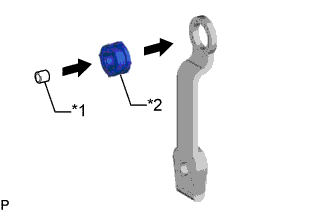
Text in Illustration *1 Spacer *2 Transmission Control Rod Grommet Install the transmission control rod grommet to the transmission control shaft lever.
-
Install the spacer to the transmission control rod grommet.
-
-
INSTALL TRANSMISSION CONTROL SHAFT LEVER
-
Install the transmission control shaft lever to the shift lever position sensor with the spring washer and nut.
- Torque:
- 16 N*m { 160 kgf*cm, 12 ft.*lbf }
-