ВЫПУСКНОЙ КОЛЛЕКТОР УСТАНОВКА

-
TEMPORARILY INSTALL NO. 2 MANIFOLD CONVERTER INSULATOR
-
Temporarily install the No. 2 manifold converter insulator to the exhaust manifold converter sub-assembly with the 2 bolts.
-
-
INSTALL NO. 1 MANIFOLD CONVERTER INSULATOR
-
Install the No. 1 manifold converter insulator to the exhaust manifold converter sub-assembly with the 5 bolts and 2 nuts.
- Torque:
- 10 N*m { 102 kgf*cm, 7 ft.*lbf }
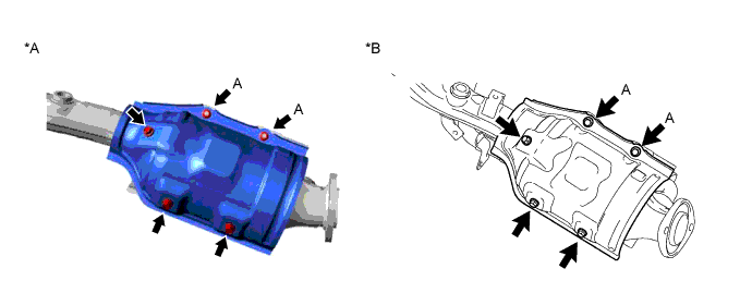
Text in Illustration *A w/o EGR System *B w/ EGR System Tech Tips
Tighten bolt A while holding the nut.
-
-
TIGHTEN NO. 2 MANIFOLD CONVERTER INSULATOR
-
Tighten the 2 bolts to install the No. 2 manifold converter insulator.
- Torque:
- 10 N*m { 102 kgf*cm, 7 ft.*lbf }
-
-
INSTALL EXHAUST MANIFOLD CONVERTER SUB-ASSEMBLY
-
w/o EGR System:
-
Set a new gasket to the cylinder head sub-assembly.
-
Temporarily install the exhaust manifold converter sub-assembly to the cylinder head sub-assembly with the 5 nuts.
-
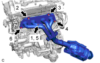
Tighten the 5 nuts in the order shown in the illustration.
- Torque:
- 62 N*m { 632 kgf*cm, 46 ft.*lbf }
-
-
w/ EGR System:
-
Set a new gasket and new EGR cooler gasket to the cylinder head sub-assembly and EGR cooler assembly.
-
Temporarily install the exhaust manifold converter sub-assembly to the cylinder head sub-assembly and EGR cooler assembly with the 2 bolts and 5 nuts.
-
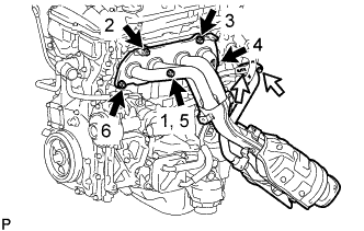
Tighten the 5 nuts in the order shown in the illustration.
- Torque:
- 62 N*m { 632 kgf*cm, 46 ft.*lbf }
Text in Illustration 
Nut 
Bolt -
Tighten the 2 bolts.
- Torque:
- 22 N*m { 224 kgf*cm, 16 ft.*lbf }
-
-
-
INSTALL NO. 1 EXHAUST MANIFOLD HEAT INSULATOR
-
Install the No. 1 exhaust manifold heat insulator to exhaust manifold converter sub-assembly with the 4 bolts.
- Torque:
- 8.0 N*m { 82 kgf*cm, 71 in.*lbf }
Note
-
The No. 1 exhaust manifold heat insulator rattles even with the bolts tightened to the specified torque.
-
Overtightening the bolts may damage the No. 1 exhaust manifold heat insulator.
-
-
INSTALL AIR FUEL RATIO SENSOR
-
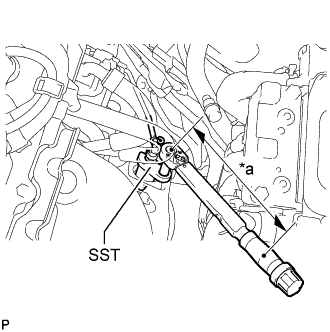
Text in Illustration *a Fulcrum Length Using SST, install the air fuel ratio sensor to the exhaust manifold converter sub-assembly.
- SST
- 09224-00010
- Torque:
- without SST
- 44 N*m { 449 kgf*cm, 32 ft.*lbf }
- with SST
- 40 N*m { 408 kgf*cm, 30 ft.*lbf }
Note
If an air fuel ratio sensor has been struck or dropped, replace it.
Tech Tips
-
Use a torque wrench with a fulcrum length of 300 mm (11.8 in.). When using a torque wrench with a fulcrum length that is not 300 mm (11.8 in.), calculate the torque specification for the torque wrench and SST based on the "without SST" torque specification.
-
Make sure SST and the wrench are connected in a straight line.
-
Perform "Inspection After Repair" after replacing an air fuel ratio sensor.
w/ EGR System: Click here
w/o EGR System: Click here
-
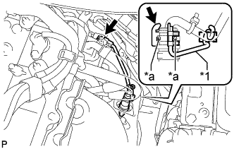
Text in Illustration *1 Wire Harness Clamp Bracket *a Air Hole Install the wire harness clamp bracket to the air fuel ratio sensor and connect the clamp.
Tech Tips
Make sure that the wire harness clamp bracket does not cover the air holes.
-
Connect the air fuel ratio sensor connector.
-
-
INSTALL ENGINE ASSEMBLY WITH TRANSMISSION
-
INSPECT FOR EXHAUST GAS LEAK
If gas is leaking, tighten the areas necessary to stop the leak. Replace damaged parts as necessary.
Tech Tips
If an exhaust gas leak has been repaired, perform an inspection following the repair.
-
w/o EGR System:
-
w/ EGR System:
-