ВПУСКНОЙ КОЛЛЕКТОР УСТАНОВКА
-
INSTALL STUD BOLT
Note
If a stud bolt is deformed or its threads are damaged, replace it.
-
Using an E6 "TORX" socket wrench, install the 4 stud bolts to the intake manifold.
- Torque:
- 4.0 N*m { 41 kgf*cm, 35 in.*lbf }
-
-
INSTALL EGR HOLE COVER PLATE (w/o EGR System)
-
Text in Illustration *a Groove *b Protrusion Install a new EGR inlet gasket and EGR hole cover plate to the intake manifold with the 2 nuts.
- Torque:
- 10 N*m { 102 kgf*cm, 7 ft.*lbf }
Note
Align the protrusion of the EGR inlet gasket with the groove of the intake manifold.
-
-
INSTALL INTAKE MANIFOLD
-
Install a new gasket to the intake manifold.
-
Temporarily install the intake manifold and intake manifold stay with the 7 bolts.
Tech Tips
If an intake manifold stay is deformed or damaged, replace it.
-
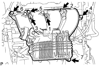
Tighten the 7 bolts in the order shown in the illustration.
- Torque:
- 28 N*m { 286 kgf*cm, 21 ft.*lbf }
-
Install the 2 wire harness clamp brackets to the intake manifold with the 3 bolts.
- Torque:
- 10 N*m { 102 kgf*cm, 7 ft.*lbf }
-
Attach the clamp to connect the No. 2 water by-pass hose to the intake manifold.
-
Attach the 7 wire harness clamps to connect the wire harness to the 2 wire harness clamp brackets and intake manifold.
-
Attach the clamp to connect the ventilation hose to the wire harness clamp bracket.
-
Connect the ventilation hose to the intake manifold, and slide the clip to secure the hose.
-
Connect the No. 2 fuel vapor feed hose to the intake manifold.
-
Attach the clamp to connect the fuel tube to the wire harness clamp bracket.
-
-
INSTALL NO. 2 EGR PIPE (w/ EGR System)
-
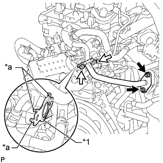
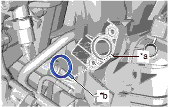
Text in Illustration *1 No. 2 EGR Pipe Gasket *a Claws 
Nut 
Bolt Install a new No. 2 EGR pipe gasket to the No. 2 EGR pipe as shown in the illustration.
Note
Make sure that the gasket is installed in the correct direction.
-
Install a new EGR inlet gasket to the intake manifold.
-
Temporarily install the No. 2 EGR pipe to the EGR valve assembly and intake manifold with the 2 bolts and 2 nuts.
Tech Tips
Tighten the bolts and nuts until they are seated on the No. 2 EGR pipe.
-
Tighten the 2 nuts while pressing the No. 2 EGR pipe against the EGR valve assembly side.
- Torque:
- 10 N*m { 102 kgf*cm, 7 ft.*lbf }
-
Tighten the 2 bolts.
- Torque:
- 25 N*m { 255 kgf*cm, 18 ft.*lbf }
-
-
INSTALL OUTLET HEATER WATER HOSE A
-
Install the water hose set to the outlet heater water hose A.
-
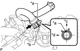
Text in Illustration *a Paint Mark *b Protrusion *c Upper Side of Vehicle *d Front Side of Vehicle Install the outlet heater water hose A to the No. 2 water by-pass pipe, and slide the hose clamp to secure the hose.
Tech Tips
The direction of the hose clamp is indicated in the illustration.
-
Connect the outlet heater water hose A to the heater unit, and slide the hose clamp to secure the hose.
-
-
CONNECT INLET HEATER WATER HOSE A
-
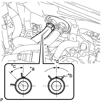
Обозначения на рисунке *a Коричневая маркировка 5 мм *b Коричневая маркировка 2 мм *c 45° +/- 15° *d 0° +/- 15° Подсоедините входной патрубок отопителя A и закрепите фиксатор.
-
-
INSTALL PURGE VSV
-
Install the purge VSV to the wire harness clamp bracket with the bolt.
- Torque:
- 18 N*m { 184 kgf*cm, 13 ft.*lbf }
-
Connect the purge VSV connector.
-
Connect the No. 2 fuel vapor feed hose to the purge VSV.
-
Connect the No. 2 fuel vapor feed hose to the purge VSV and slide the clip to secure the hose.
-
-
INSTALL VACUUM SENSOR ASSEMBLY
-
Install the vacuum sensor assembly to the intake manifold with the bolt.
- Torque:
- 10 N*m { 102 kgf*cm, 7 ft.*lbf }
Note
If a vacuum sensor assembly has been struck or dropped, replace it.
-
Connect the vacuum sensor assembly connector.
-
-
CONNECT INVERTER RESERVE TANK ASSEMBLY (for RHD)
-
Install the inverter reserve tank assembly to the No. 1 inverter reserve tank bracket with the 2 bolts.
- Torque:
- 13 N*m { 127 kgf*cm, 9 ft.*lbf }
-
-
INSTALL INJECTOR DRIVER
-
INSTALL THROTTLE BODY WITH MOTOR ASSEMBLY
-
INSTALL NO. 1 AIR CLEANER INLET
-
Установите входной патрубок воздушного фильтра № 1 и закрепите его болтом.
- Torque:
- 5,0 Н*м { 51 кгс*см, 44 фунт-сила-дюйма }
-
-
INSTALL COOL AIR INTAKE DUCT SEAL
-
Установите сальник впускного воздухопровода холодного воздуха и закрепите его 7 фиксаторами.
-
-
INSTALL ENGINE ROOM SIDE COVER
-
Установите боковую крышку моторного отсека и закрепите ее 4 фиксаторами.
-