БЛОК ДВИГАТЕЛЯ ПОВТОРНАЯ СБОРКА

-
INSTALL STRAIGHT PIN
Note
If a straight pin is deformed or damaged, replace it.
-
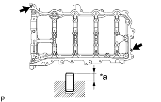
Text in Illustration *a Protrusion Height Using a plastic-faced hammer, install 2 new straight pins.
Standard protrusion height 5.0 to 7.0 mm (0.197 to 0.276 in.)
-
-
INSTALL RING PIN
Note
If a ring pin is deformed or damaged, replace it.
-
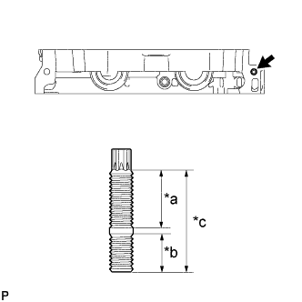
Stiffening crankcase assembly lower side:
-
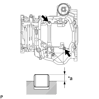
Text in Illustration *a Protrusion Height Using a plastic-faced hammer, install 2 new ring pins.
Standard protrusion height 4.3 to 5.3 mm (0.169 to 0.209 in.)
-
-
Camshaft housing sub-assembly lower side:
-
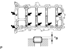
Text in Illustration *a Protrusion Height Using a plastic-faced hammer, install 8 new ring pins.
Standard protrusion height 2.7 to 3.3 mm (0.106 to 0.130 in.)
-
-
-
INSTALL STUD BOLT
Note
If a stud bolt is deformed or the threads are damaged, replace it.
-
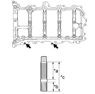
Timing chain cover sub-assembly front side:
-
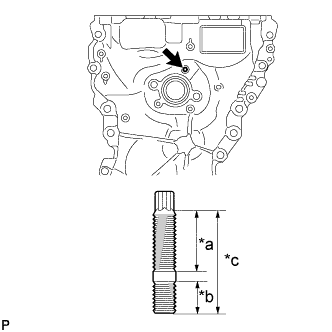
Text in Illustration *a 16 mm (0.630 in.) *b 9 mm (0.354 in.) *c 27 mm (1.06 in.) Using an E6 "TORX" socket wrench, install the stud bolt.
- Torque:
- 4.0 N*m { 41 kgf*cm, 35 in.*lbf }
-
-
Stiffening crankcase assembly lower and LH sides:
-
Using an E5 and E8 "TORX" socket wrench, install the 4 stud bolts.
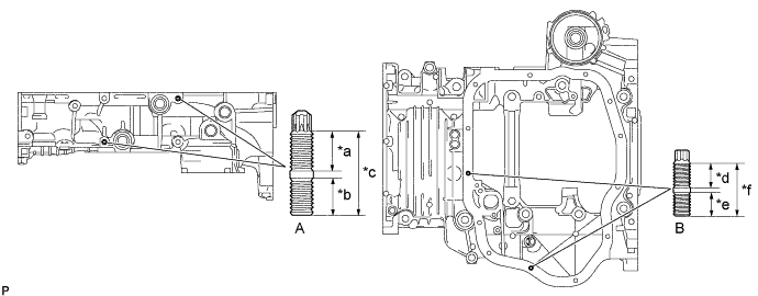
Test in Illustration *a 14 mm (0.551 in.) *b 13 mm (0.512 in.) *c 29 mm (1.14 in.) *d 8.5 mm (0.334 in.) *e 8.0 mm (0.315 in.) *f 18 mm (0.709 in.) - Torque:
- for Stud Bolt A
- 6.5 N*m { 66 kgf*cm, 58 in.*lbf }
- for Stud Bolt B
- 4.0 N*m { 41 kgf*cm, 35 in.*lbf }
-
-
Camshaft housing sub-assembly front side:
-
When reusing the camshaft housing stud bolts:
Apply adhesive 1324 to the threaded portion (camshaft housing sub-assembly side) of the stud bolt.
Adhesive Toyota Genuine Adhesive 1324, Three Bond 1324 or equivalent Note
Install the stud bolt within 3 minutes of applying adhesive.
-
Text in Illustration *a 20 mm (0.787 in.) *b 13 mm (0.512 in.) *c 35 mm (1.38 in.) Using an E8 "TORX" socket wrench, install the stud bolt.
- Torque:
- 6.5 N*m { 66 kgf*cm, 58 in.*lbf }
-
-
Camshaft housing sub-assembly upper side:
-
Text in Illustration *a 16 mm (0.630 in.) *b 9 mm (0.354 in.) *c 27 mm (1.06 in.) Using an E6 "TORX" socket wrench, install the 2 stud bolts.
- Torque:
- 4.0 N*m { 41 kgf*cm, 35 in.*lbf }
-
-
Cylinder head cover sub-assembly upper side:
-
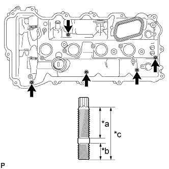
Text in Illustration *a 16 mm (0.630 in.) *b 9 mm (0.354 in.) *c 27 mm (1.06 in.) Using an E6 "TORX" socket wrench, install the 5 stud bolts.
- Torque:
- 4.0 N*m { 41 kgf*cm, 35 in.*lbf }
-
-
-
SET ENGINE BALANCER ASSEMBLY
-
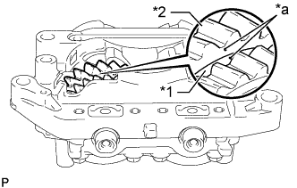
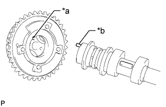
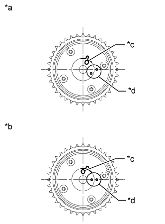
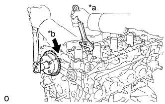
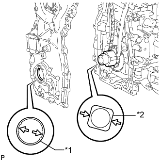
Text in Illustration *1 Balance Shaft Damper Cover *2 No. 1 Balance Shaft Driven Gear *a Alignment Mark Make sure that the alignment marks on the No. 1 balance shaft driven gear and No. 2 balance shaft driven gear are aligned.
-
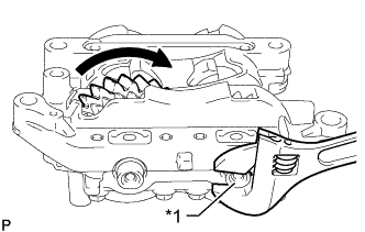
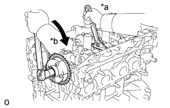
Text in Illustration *1 No. 2 Balance Shaft If the alignment marks are not aligned, hold the No. 2 balance shaft with a wrench at its flat portions, and rotate the No. 1 balance shaft as shown in the illustration to align the marks.
-
-
INSTALL STIFFENING CRANKCASE ASSEMBLY
-
Clean the bolts and their installation holes.
-
Clean and degrease the contact surfaces of the cylinder block sub-assembly and stiffening crankcase assembly.
-
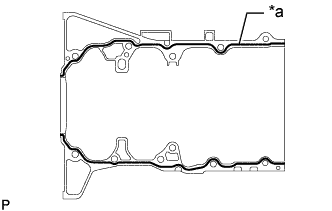
Text in Illustration *a Seal Packing Apply seal packing in a continuous line as shown in the illustration.
Seal packing Toyota Genuine Seal Packing Black, Three Bond 1207B or equivalent Standard seal diameter 2.5 to 3.5 mm (0.0984 to 0.1378 in.) Note
-
Install the stiffening crankcase assembly within 3 minutes and tighten the bolts within 10 minutes after applying seal packing.
-
Do not add engine oil within 2 hours of installation.
-
Do not start the engine for at least 2 hours after the installation.
-
-
Align the pins on the cylinder block sub-assembly with the holes in the stiffening crankcase assembly, and then install the stiffening crankcase assembly to the cylinder block sub-assembly.
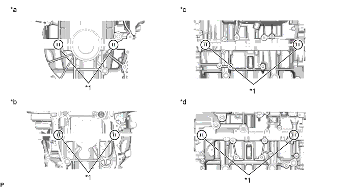
Test in Illustration *1 Straight Pin - - *a Rear Side *b Front Side *c RH Side *d LH Side -
After installing the stiffening crankcase assembly, check that the seal packing has come out at the locations shown in the illustration.
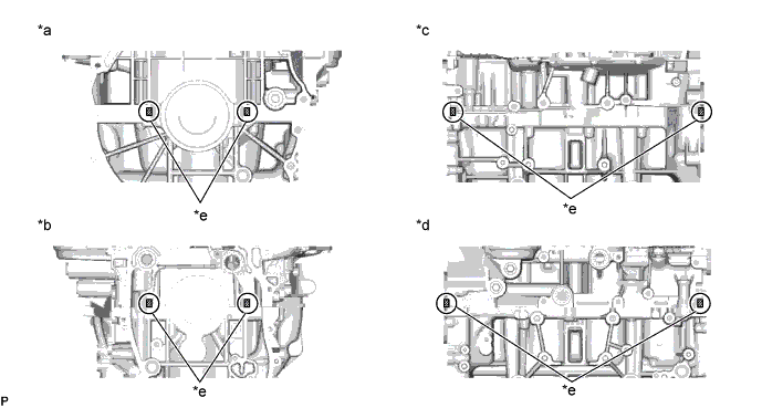
Test in Illustration *a Rear Side *b Front Side *c RH Side *d LH Side *e Areas where the seal packing comes out - - Note
If the seal packing does not come out, reapply seal packing and install the stiffening crankcase assembly.
-
Wipe off the seal packing that comes out at the joint of the stiffening crankcase assembly and the cylinder block sub-assembly.
Note
Wipe off the seal packing within 5 minutes after installing the stiffening crankcase assembly.
-
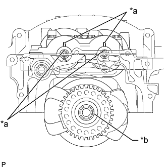
Text in Illustration *a Timing Mark *b Crankshaft Pulley Set Crankshaft Key Groove Align the crankshaft pulley set crankshaft key groove, timing marks on the balance shaft and balance shaft housing as shown in the illustration, and then set the stiffening crankcase assembly on the cylinder block sub-assembly.
-
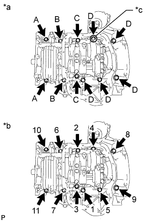
Text in Illustration *a Bolt Type *b Tightening sequence *c Apply Adhesive 1344 Apply adhesive 1344 to the threaded portion of bolt D (*c) shown in the illustration.
Adhesive Toyota Genuine Adhesive 1344, Three Bond 1344 or equivalent Note
Install the bolt within 3 minutes of applying adhesive.
-
Temporarily install the stiffening crankcase assembly with the 11 bolts.
-
Tighten the 11 bolts in the sequence shown in the illustration.
- Torque:
- for Bolt A
- 24 N*m { 245 kgf*cm, 18 ft.*lbf }
- except Bolt A
- 43 N*m { 438 kgf*cm, 32 ft.*lbf }
Bolt Length Item Length Diameter Bolt A 65 mm (2.56 in.) 8 mm (0.315 in.) Bolt B 65 mm (2.56 in.) 10 mm (0.394 in.) Bolt C 140 mm (5.51 in.) Bolt D 125 mm (4.92 in.) Bolt E 35 mm (1.38 in.) -
Tighten the bolt.
- Torque:
- 24 N*m { 245 kgf*cm, 18 ft.*lbf }
-
Temporarily install the crankshaft pulley set bolt.
-
Text in Illustration *a No. 1 Cylinder TDC/Compression *b Crankshaft Pulley Set Crankshaft Key Groove Rotate the crankshaft clockwise to set the No. 1 cylinder TDC/Compression.
-
Remove the crankshaft pulley set bolt.
-
-
INSTALL NO. 1 OIL PAN BAFFLE PLATE
-
Install the No. 1 oil pan baffle plate with the 4 bolts.
- Torque:
- 10 N*m { 102 kgf*cm, 7 ft.*lbf }
-
-
INSTALL OIL STRAINER SUB-ASSEMBLY
-
Apply a light coat of engine oil to a new gasket.
-
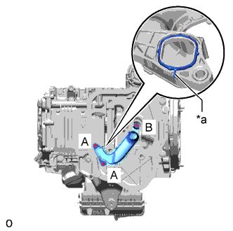
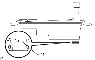
Text in Illustration *a Protrusion Align the protrusion of the gasket with the cutout of the oil strainer sub-assembly, and install the gasket to the oil strainer sub-assembly.
-
Temporarily install the oil strainer sub-assembly with the 3 bolts.
-
Tighten the 2 bolts labeled A.
- Torque:
- 10 N*m { 102 kgf*cm, 7 ft.*lbf }
-
Tighten the bolt labeled B.
- Torque:
- 10 N*m { 102 kgf*cm, 7 ft.*lbf }
-
-
INSTALL OIL PAN SUB-ASSEMBLY
-
Clean and degrease the contact surfaces of the oil pan sub-assembly and stiffening crankcase assembly.
-
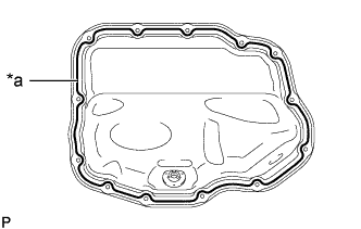
Text in Illustration *a Seal Packing Apply seal packing in a continuous line as shown in the illustration.
Seal packing Toyota Genuine Seal Packing Black, Three Bond 1207B or equivalent Standard seal diameter 2.5 to 3.5 mm (0.0984 to 0.138 in.) Note
-
Install the stiffening crankcase assembly within 3 minutes and tighten the bolts and nuts within 10 minutes after applying seal packing.
-
Do not add engine oil within 2 hours of installation.
-
Do not start the engine for at least 2 hours after the installation.
-
-
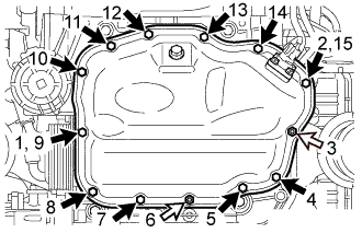
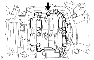
Install the oil pan sub-assembly with the 11 bolts and 2 nuts in several steps, in the sequence shown in the illustration.
- Torque:
- 10 N*m { 102 kgf*cm, 7 ft.*lbf }
Text in Illustration 
Bolt 
Nut
-
-
INSTALL OIL PAN DRAIN PLUG
-
Install a new gasket and the oil pan drain plug.
- Torque:
- 40 N*m { 408 kgf*cm, 30 ft.*lbf }
-
-
INSTALL OIL COOLER ASSEMBLY
-
Apply a light coat of engine oil to 2 new O-rings.
-
Install the 2 O-rings to the stiffening crankcase assembly.
-
Temporarily install the oil cooler assembly with the 2 nuts and 2 bolts.
-
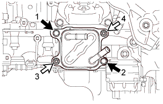
Tighten the 2 bolts and 2 nuts in the order shown in the illustration.
- Torque:
- 21 N*m { 214 kgf*cm, 15 ft.*lbf }
Text in Illustration Bolt Nut -
Connect the No. 8 water by-pass hose to the oil cooler assembly, and slide the clamp to secure the hose.
-
Connect the No. 7 water by-pass hose to the oil cooler assembly, and slide the clamp to secure the hose.
-
-
INSTALL ENGINE OIL LEVEL SENSOR
-
Clean the engine oil level sensor installation area in the oil pan sub-assembly.
-
Install a new gasket to the engine oil level sensor.
-
Install the engine oil level sensor with the 4 bolts.
- Torque:
- 8.2 N*m { 84 kgf*cm, 73 in.*lbf }
-
Connect the engine oil level sensor connector.
-
-
INSTALL OIL FILTER CAP ASSEMBLY
-
Clean the inside of the oil filter cap assembly, the threads and O-ring groove.
-
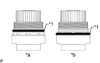
Text in Illustration *1 O-Ring *a Correct *b Incorrect Apply a small amount of engine oil to a new O-ring and install it to the oil filter cap assembly.
Note
-
Be sure to install the O-ring in the proper position, otherwise engine oil may leak.
-
Do not twist the O-ring.
-
-
Set a new oil filter element in the oil filter cap assembly.
-
Remove any dirt or foreign matter from the installation surface of the engine.
-
Apply a light coat of engine oil to the O-ring of the oil filter cap assembly again.
Note
Make sure that the O-ring does not get caught between the parts.
-
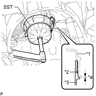
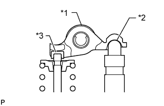
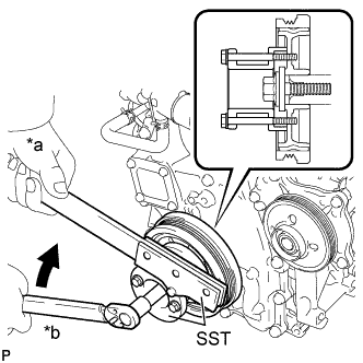
Text in Illustration *1 Stiffening Crankcase Assembly *2 O-Ring *3 Oil Filter Cap Assembly *a No Gap Using SST, tighten the oil filter cap assembly to the stiffening crankcase assembly.
- SST
- 09228-06501
- Torque:
- 25 N*m { 255 kgf*cm, 18 ft.*lbf }
Note
-
After tightening the oil filter cap assembly, make sure that there is no gap and that the O-ring is not protruding.
-
Do not remove the oil filter bracket clip when installing the oil filter cap assembly.
-
Do not cross thread the oil filter cap assembly.
-
Apply a light coat of engine oil to a new O-ring and install it to the oil filter cap assembly.
Note
Remove any dirt or foreign matter from the installation surface.
-
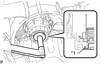
Text in Illustration *1 O-Ring Install the oil filter drain plug to the oil filter cap assembly.
- Torque:
- 13 N*m { 127 kgf*cm, 9 ft.*lbf }
Note
Make sure that the O-ring does not get caught between the parts.
-
-
INSTALL REAR ENGINE OIL SEAL
-
Apply MP grease to the lip of a new rear engine oil seal.
Note
-
Keep the lip free from foreign matter.
-
Do not allow MP grease to contact the dust seal.
-
-
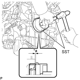
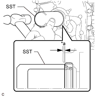
Text in Illustration *a Depth Using SST and a hammer, tap in the rear engine oil seal until its surface is flush with the edges of the cylinder block sub-assembly and stiffening crankcase assembly.
- SST
- 09223-15030
- 09950-70010 ( 09951-07150 )
Standard depth 0 to 0.9 mm (0 to 0.0354 in.) Note
-
Do not tap in the rear engine oil seal at an angle.
-
Keep the lip free from foreign matter.
-
Wipe off any MP grease from the crankshaft.
-
-
INSTALL CYLINDER BLOCK WATER JACKET SPACER
-
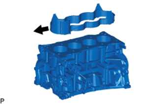
Install the cylinder block water jacket spacer to the cylinder block sub-assembly.
Text in Illustration Engine front side
-
-
INSTALL CYLINDER HEAD GASKET
-
Remove any old packing (FIPG) material and be careful not to drop any oil on the contact surfaces of the cylinder head sub-assembly or cylinder block sub-assembly.
-
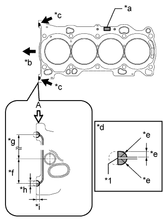
Text in Illustration *1 Cylinder Head Gasket *a Lot No. *b Engine Front Side *c Seal Packing *d View A *e 3.0 to 5.0 mm (0.118 to 0.197 in.) *f 38 mm (1.50 in.) *g 152.5 mm (6.00 in.) *h 7.0 to 9.0 mm (0.276 to 0.354 in.) *i 5.0 to 7.0 mm (0.197 to 0.276 in.) Apply seal packing to a new cylinder head gasket as shown in the illustration.
Seal packing Toyota Genuine Seal Packing Black, Three Bond 1207B or equivalent. Note
-
Be sure to clean and degrease the contact surfaces.
-
Install the cylinder head gasket within 3 minutes and tighten the cylinder head set bolts within 15 minutes after applying seal packing.
-
-
-
INSTALL CYLINDER HEAD SUB-ASSEMBLY
Tech Tips
The cylinder head set bolts are tightened in 4 progressive steps.
-
Place the cylinder head sub-assembly on the cylinder block sub-assembly.
Note
-
Check and clean the cylinder head set bolts and their installation holes.
-
Make sure that no oil is on the mounting surface of the cylinder head sub-assembly.
-
Gently place the cylinder head sub-assembly in order not to damage the cylinder head gasket.
-
-
Apply a light coat of engine oil to the threads and under the heads of the cylinder head set bolts.
-
Install the 10 plate washers to the 10 cylinder head set bolts.
-
Step 1:
-
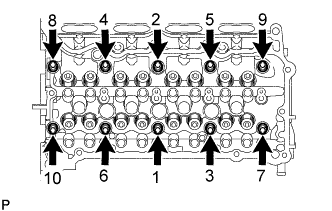
Using a 10 mm bi-hexagon wrench, install and uniformly tighten the 10 cylinder head set bolts in several steps, in the sequence shown in the illustration.
- Torque:
- 36 N*m { 367 kgf*cm, 27 ft.*lbf }
Note
-
Install the cylinder head set bolt to the same place it was removed from.
-
Be careful not to drop the plate washers into the cylinder head sub-assembly.
-
-
Step 2:
-
Tighten the cylinder head set bolts again in the sequence shown in the illustration to make sure that they are tightened to the specified torque.
- Torque:
- 36 N*m { 367 kgf*cm, 27 ft.*lbf }
-
-
Step 3:
-
Mark the front side of each cylinder head set bolt head with paint.
-
Tighten the cylinder head set bolts an additional 90°.
-
-
Step 4:
-
Tighten the cylinder head set bolts an additional 90°.
-
Check that the paint marks are now at a 180° angle to the front.
Note
After installing the cylinder head sub-assembly, wipe off any excess seal packing within 5 minutes.
-
-
-
INSTALL VALVE STEM CAP
-
Apply a light coat of engine oil to the valve stem caps.
-
Install the 16 valve stem caps to the valve stem ends.
Note
-
Install the valve stem cap to the same place it was removed from.
-
Do not drop the valve stem caps into the cylinder head sub-assembly.
-
-
-
INSTALL VALVE LASH ADJUSTER ASSEMBLY
Note
-
Keep the valve lash adjuster assembly free from dirt and foreign objects.
-
Only use clean engine oil.
-
If the valve lash adjuster assembly is tilted after bleeding, oil will leak. Make sure to bleed the valve lash adjuster assembly again.
-
Bleed the valve lash adjuster assembly Click here.
-
If the plunger moves, bleed the valve lash adjuster assembly again.
-
Place the valve lash adjuster assembly into a container full of new engine oil, and then fill the low pressure chamber with engine oil.
-
Apply engine oil to the outer surface of the valve lash adjuster body and the tip of the plunger, and then install the valve lash adjuster assembly while turning it.
Note
Install the valve lash adjuster assembly to the same place it was removed from.
-
-
INSTALL NO. 1 VALVE ROCKER ARM SUB-ASSEMBLY
-
Apply engine oil to the valve lash adjuster assembly tips and valve stem caps.
-
Text in Illustration *1 No. 1 Valve Rocker Arm Sub-assembly *2 Valve Lash Adjuster Assembly *3 Valve Stem Cap Install the 16 No. 1 valve rocker arm sub-assemblies as shown in the illustration.
Note
Install the No. 1 valve rocker arm sub-assembly to the same place it was removed from.
-
-
INSTALL NO. 2 CAMSHAFT BEARING
-
Clean the No. 2 camshaft bearing.
Note
Do not apply engine oil to the No. 2 camshaft bearing or contact surfaces.
-
Install the No. 2 camshaft bearing to the camshaft housing sub-assembly.
-
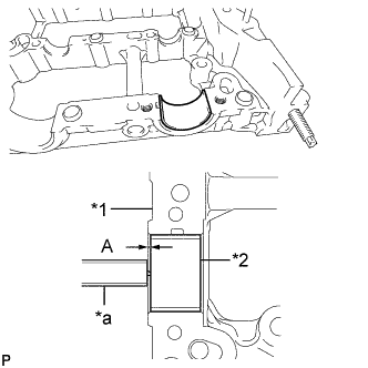
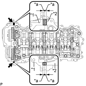
Text in Illustration *1 Camshaft Housing Sub-assembly *2 No. 2 Camshaft Bearing *a Vernier Caliper Using a vernier caliper, measure the distance between the camshaft housing sub-assembly edge and the No. 2 camshaft bearing edge.
Standard distance A = 1.15 to 1.85 mm (0.0453 to 0.0728 in.)
-
-
INSTALL NO. 2 CAMSHAFT
Tech Tips
Perform "Inspection After Repair" after replacing the No. 2 camshaft.
-
w/ EGR System: Click here
-
w/o EGR System: Click here
-
Clean the No. 2 camshaft journals and camshaft housing sub-assembly.
-
Apply a light coat of engine oil to the No. 2 camshaft journals and camshaft housing sub-assembly.
-
Set the No. 2 camshaft to the camshaft housing sub-assembly.
-
-
INSTALL CAMSHAFT
Tech Tips
Perform "Inspection After Repair" after replacing the camshaft.
-
w/ EGR System: Click here
-
w/o EGR System: Click here
-
Clean the camshaft journals and camshaft housing sub-assembly.
-
Apply a light coat of engine oil to the camshaft journals and camshaft housing sub-assembly.
-
Set the camshaft to the camshaft housing sub-assembly.
-
-
INSTALL NO. 1 CAMSHAFT BEARING
-
Clean the No. 1 camshaft bearing.
Note
Do not apply engine oil to the No. 1 camshaft bearing or contact surfaces.
-
Install the No. 1 camshaft bearing to the No. 1 camshaft bearing cap.
-
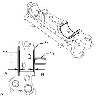
Text in Illustration *1 No. 1 Camshaft Bearing Cap *2 No. 1 Camshaft Bearing *a Vernier Caliper Using a vernier caliper, measure the distance between the No. 1 camshaft bearing cap edge and the No. 1 camshaft bearing edge.
Standard dimension A - B or B - A = 0 to 0.7 mm (0 to 0.0276 in.)
-
-
INSTALL OIL CONTROL VALVE FILTER
-
Check that there is no foreign matter on the mesh section.
-
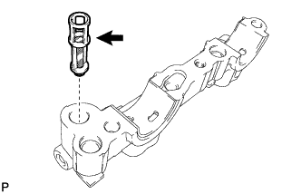
Install the oil control valve filter to the No. 1 camshaft bearing cap.
Note
Do not touch the mesh section on the oil control valve filter.
-
-
INSTALL CAMSHAFT BEARING CAP
-
Clean the camshaft bearing caps.
-
Apply a light coat of engine oil to the camshaft journals and camshaft bearing caps.
-
Install the No. 1 camshaft bearing cap, No. 2 camshaft bearing cap, No. 3 camshaft bearing cap and No. 4 camshaft bearing cap.
-
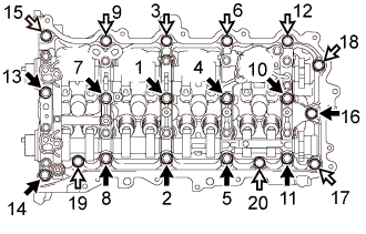
Text in Illustration *1 No. 1 camshaft bearing cap *2 No. 2 camshaft bearing cap *3 No. 3 camshaft bearing cap *4 No. 4 camshaft bearing cap Using several steps, uniformly tighten the 11 bolts in the sequence shown in the illustration.
- Torque:
- 16 N*m { 163 kgf*cm, 12 ft.*lbf }
Note
After installing the No. 1 camshaft bearing cap, No. 2 camshaft bearing cap, No. 3 camshaft bearing cap and No. 4 camshaft bearing cap, make sure that the camshaft and No. 2 camshaft rotate smoothly.
-
-
INSTALL CAMSHAFT HOUSING SUB-ASSEMBLY
-
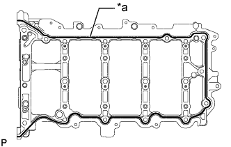
Text in Illustration *a Seal Packing Apply seal packing in a continuous line as shown in the illustration.
Seal packing Toyota Genuine Seal Packing Black, Three Bond 1207B or equivalent Standard seal diameter 3.0 to 4.0 mm (0.118 to 0.157 in.) Note
-
Remove any oil from the contact surface.
-
Check the bolts and bolt holes and clean them.
-
Install the camshaft housing sub-assembly within 3 minutes and tighten the bolts within 10 minutes after applying seal packing.
-
Do not add engine oil within 2 hours of installation.
-
Do not start the engine for at least 2 hours after the installation.
-
-
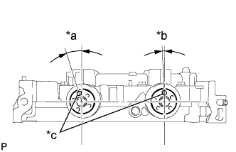
Text in Illustration *a Approximately 17° *b Approximately 2° *c Knock Pin Position the knock pin of the camshaft and No. 2 camshaft as shown in the illustration.
-
Text in Illustration *1 No. 1 Valve Rocker Arm Sub-assembly *2 Valve Lash Adjuster Assembly *3 Valve Stem Cap Make sure that the No. 1 valve rocker arm sub-assemblies are installed as shown in the illustration.
-
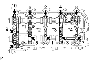
Install the camshaft housing sub-assembly, and then tighten the 20 bolts in the order shown in the illustration.
- Torque:
- 27 N*m { 275 kgf*cm, 20 ft.*lbf }
Standard Bolt Item Length Bolt A 70 mm (2.76 in.) Bolt B 45 mm (1.77 in.) Text in Illustration Bolt A Bolt B Note
If the bolts have been loosened during the installation, apply seal packing black to the camshaft housing sub-assembly again.
-
-
INSTALL OIL PIPE SUB-ASSEMBLY
-
Install the oil pipe sub-assembly with the bolt.
- Torque:
- 10 N*m { 102 kgf*cm, 7 ft.*lbf }
-
-
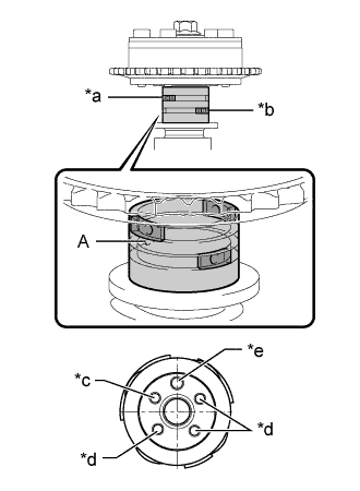
INSPECT CAMSHAFT TIMING EXHAUST GEAR ASSEMBLY
-
Secure the No. 2 camshaft between aluminum plates in a vise.
Note
Do not damage the No. 2 camshaft.
-
Install the camshaft timing exhaust gear assembly to the No. 2 camshaft Click here.
-
Release the lock pin.
-
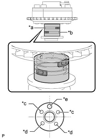
Text in Illustration *a Advance Side Path *b Retard Side Path *c Open *d Close *e Knock Pin 
Rubber Piece 
Vinyl Tape Clean the No. 2 camshaft journal with non-residue solvent.
-
Cover the 4 oil paths of the cam journal with vinyl tape as shown in the illustration.
Tech Tips
There are 4 oil paths in the grooves of the No. 2 camshaft. Plug 2 paths with rubber pieces.
-
Make a hole in the vinyl tape placed over the 2 oil holes that are not plugged with rubber pieces.
-
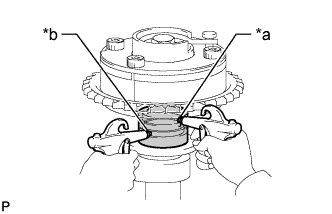
Text in Illustration *a Advance Side Path *b Retard Side Path Apply approximately 200 kPa (2.0 kgf/cm2, 29 psi) of air pressure to the 2 open paths (the advance side path and retard side path).
Note
Cover the paths with a piece of cloth when applying pressure to keep oil from spraying.
-
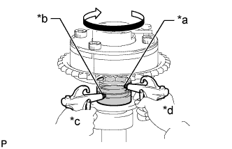
Text in Illustration *a Advance Side Path *b Retard Side Path *c Hold Pressure *d Decompress Check that the camshaft timing exhaust gear assembly turns in the retard direction when reducing the air pressure applied to the advance side path.
Tech Tips
The lock pin is released and the camshaft timing exhaust gear assembly turns in the retard direction.
-
When the camshaft timing exhaust gear assembly moves to the most retarded position, release the air pressure from the advance side path, and then release the air pressure from the retard side path.
Note
Be sure to release the air pressure from the advance side path first. If the air pressure of the retard side path is released first, the camshaft timing exhaust gear assembly may abruptly shift in the advance direction and break the lock pin or other parts.
-
-
Check for smooth rotation.
-
Turn the camshaft timing exhaust gear assembly within its movable range (21.5 to 23.5°) 2 or 3 times, but do not turn it to the most advanced position. Make sure that the gear turns smoothly.
Note
When the air pressure is released from the advance side path and then from the retard side path, the gear automatically returns to the most advanced position due to the advance assist spring operation, and locks. Gradually release the air pressure from the retard side path before performing the smooth rotation check.
-
-
Remove the vinyl tape and rubber pieces from the No. 2 camshaft.
-
Remove the bolt and camshaft timing exhaust gear assembly Click here.
-
Place the chain sub-assembly around the camshaft timing exhaust gear assembly.
-
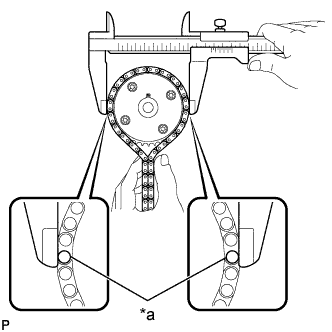
Inspect the camshaft timing exhaust gear assembly diameter.
-
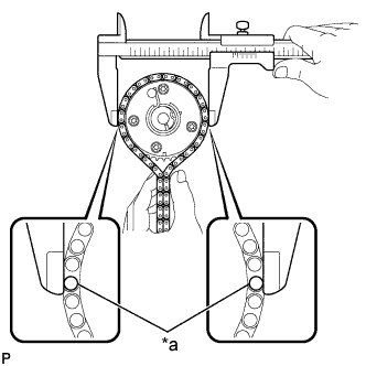
Text in Illustration *a Chain Roller Using a vernier caliper, measure the camshaft timing exhaust gear assembly diameter with the chain sub-assembly.
Minimum diameter (with chain sub-assembly) 115.12 mm (4.53 in.) Tech Tips
The vernier caliper must contact the chain rollers for the measurement.
If the diameter is less than the minimum, replace the chain sub-assembly and camshaft timing exhaust gear assembly.
-
-
-
INSTALL CAMSHAFT TIMING EXHAUST GEAR ASSEMBLY
Tech Tips
Perform "Inspection After Repair" after replacing the camshaft timing exhaust gear assembly.
-
w/ EGR System: Click here
-
w/o EGR System: Click here
-
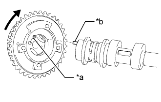
Text in Illustration *a Pin Hole *b Knock Pin Align and attach the knock pin of the No. 2 camshaft with the pin hole of the camshaft timing exhaust gear assembly.
Note
Do not forcefully press the camshaft timing exhaust gear assembly. Otherwise, the tip of knock pin of the No. 2 camshaft may damage the seal surface of the camshaft timing exhaust gear assembly, leading to poor sealing.
-
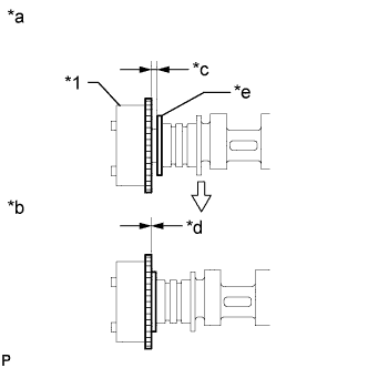
Text in Illustration *1 Camshaft Timing Exhaust Gear Assembly *a Incorrect *b Correct *c Clearance *d No Clearance *e Camshaft Flange Check that there is no clearance between the camshaft timing exhaust gear assembly and camshaft flange.
-
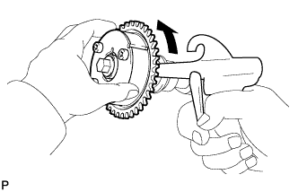
Text in Illustration *a Hold *b Turn Using a wrench to hold the hexagonal portion of the No. 2 camshaft, tighten the bolt.
- Torque:
- 85 N*m { 867 kgf*cm, 63 ft.*lbf }
Note
Be careful not to damage the camshaft housing sub-assembly or spark plug tube with the wrench.
-
-
INSPECT CAMSHAFT TIMING GEAR ASSEMBLY
-
Secure the camshaft between aluminum plates in a vise.
Note
Do not damage the camshaft.
-
Install the camshaft timing gear assembly to the camshaft Click here.
-
Check the lock of the camshaft timing gear assembly.
-
Text in Illustration *a Lock Pin Released *b Lock Pin Locked *c Pin Hole *d Lock Check Point Make sure that the camshaft timing gear assembly is locked.
-
-
Release the lock pin.
-
Text in Illustration *a Retard Side Path *b Advance Side Path *c Open *d Close *e Knock Pin Rubber Piece Vinyl Tape Clean the camshaft journal with non-residue solvent.
-
Cover the 4 oil paths of the cam journal with vinyl tape as shown in the illustration.
Tech Tips
There are 4 oil paths in the grooves of the camshaft. Plug 3 of the paths with pieces of rubber.
-
Open a hole at port A shown in the illustration.
-
While applying approximately 200 kPa (2.0 kgf/cm2, 29 psi) of air pressure to the oil path, forcibly turn the camshaft timing gear assembly in the advance direction (counterclockwise).
Note
-
Cover the paths with a piece of cloth when applying pressure to keep oil from spraying.
-
Do not allow the camshaft timing gear assembly to lock. If it locks, release the lock pin again.
Tech Tips
-
The camshaft timing gear assembly may be turned in the advance direction without applying any force.
-
If enough air pressure cannot be applied because of air leakage from the port, releasing the lock pin may be difficult.
-
-
-
Check for smooth rotation.
-
Turn the camshaft timing gear assembly within its movable range (26.5 to 28.5°) 2 or 3 times, but do not turn it to the most retarded position. Make sure that the gear turns smoothly.
Note
Do not allow the camshaft timing gear assembly to lock. If it locks, release the lock pin again.
-
-
Remove the vinyl tape and rubber pieces from the camshaft.
-
Remove the bolt and camshaft timing gear assembly Click here.
-
Place the chain sub-assembly around the camshaft timing gear assembly.
-
Inspect the camshaft timing gear assembly diameter.
-
Text in Illustration *a Chain Roller Using a vernier caliper, measure the camshaft timing gear assembly diameter with the chain sub-assembly.
Minimum diameter (with chain sub-assembly) 115.12 mm (4.53 in.) Tech Tips
The vernier caliper must contact the chain rollers for the measurement.
If the diameter is less than the minimum, replace the chain sub-assembly and camshaft timing gear assembly.
-
-
-
INSTALL CAMSHAFT TIMING GEAR ASSEMBLY
Tech Tips
Perform "Inspection After Repair" after replacing the camshaft timing gear assembly.
-
w/ EGR System: Click here
-
w/o EGR System: Click here
-
When using a new camshaft timing gear assembly:
-
Text in Illustration *a Lock Pin Released *b Lock Pin Locked *c Pin Hole *d Lock Check Point Check that the camshaft timing gear assembly is not locked.
Note
If locked, release the lock pin of the camshaft timing gear assembly Click here.
-
-
Text in Illustration *a Pin Hole *b Knock Pin When reusing the camshaft timing gear assembly:
-
Release the lock pin Click here.
-
-
Put the camshaft timing gear assembly and camshaft together by aligning the pin hole and knock pin.
-
Lightly press and turn the camshaft timing gear assembly against the camshaft, and press harder after the knock pin enters the pin hole.
Note
-
Be sure not to turn the camshaft timing gear assembly in the advanced direction.
-
Do not forcefully press the camshaft timing gear assembly. Otherwise, the tip of knock pin of the camshaft may damage the seal surface of the camshaft timing gear assembly, leading to poor sealing.
-
-
Text in Illustration *1 Camshaft Timing Gear Assembly *a Incorrect *b Correct *c Clearance *d No Clearance *e Camshaft Flange Check that there is no clearance between the camshaft timing gear assembly and camshaft flange.
-
Text in Illustration *a Hold *b Turn Using a wrench to hold the hexagonal portion of the camshaft, tighten the bolt.
- Torque:
- 85 N*m { 867 kgf*cm, 63 ft.*lbf }
Note
-
Be careful not to damage the camshaft housing sub-assembly or spark plug tube with the wrench.
-
If the camshaft timing gear assembly has been locked at the most retarded position, release the lock pin first, and then tighten the bolt.
-
The lock pin may be damaged if the bolt is tightened when the camshaft timing gear assembly is locked.
-
-
INSTALL CRANKSHAFT PULLEY SET CRANKSHAFT KEY
-
Install the 2 crankshaft pulley set crankshaft keys to the crankshaft.
-
-
INSTALL CRANKSHAFT TIMING GEAR OR SPROCKET
-
Align the crankshaft timing gear or sprocket groove with crankshaft pulley set crankshaft key, and install the crankshaft timing gear or sprocket to the crankshaft.
-
-
POUR ENGINE OIL
Note
-
Oil must be added if the valve lash adjuster assemblies or No. 1 valve rocker arm sub-assemblies were removed.
-
Make sure that the oil passage is full of engine oil.
-
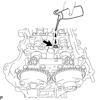
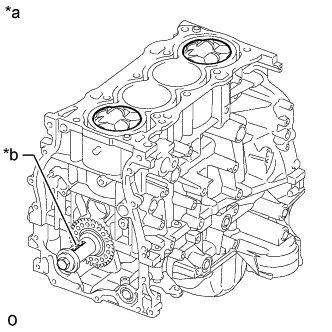
Pour 100 cc (6.1 cu. in.) of engine oil into the oil hole shown in the illustration.
-
-
INSTALL NO. 1 CHAIN VIBRATION DAMPER
-
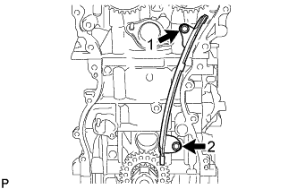
Install the No. 1 chain vibration damper by tightening the 2 bolts in the order shown in the illustration.
- Torque:
- 21 N*m { 214 kgf*cm, 15 ft.*lbf }
-
-
INSTALL CHAIN SUB-ASSEMBLY
-
Temporarily install the crankshaft pulley set bolt.
-
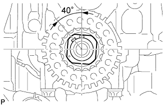
Rotate the crankshaft 40° counterclockwise.
-
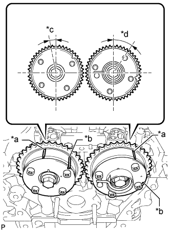
Text in Illustration *a Timing Mark *b Identification Groove *c Approximately 7° *d Approximately 32° Check that the timing marks of the camshaft timing gears are as shown in the illustration.
Tech Tips
The camshaft timing gear assembly and the camshaft timing exhaust gear assembly have both timing marks and identification grooves. Use the timing marks for alignment.
-
Place the chain sub-assembly onto the camshaft timing gears and crankshaft timing gear or sprocket.
Note
-
Make sure the mark plate of the chain sub-assembly faces away front of the engine.
-
It is not necessary to install the chain sub-assembly to the teeth of the camshaft timing gears and crankshaft timing gear or sprocket.
-
-
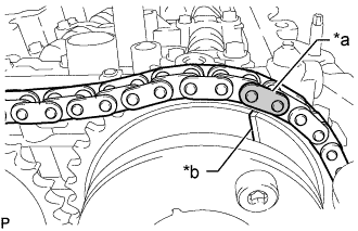
Text in Illustration *a Mark Plate (Orange) *b Timing Mark Align the mark plate (orange) of the chain sub-assembly with the timing mark of the camshaft timing exhaust gear assembly and install the chain sub-assembly to the camshaft timing exhaust gear assembly.
-
Text in Illustration *a Mark Plate (Yellow) *b Timing Mark Align the mark plate (yellow) of the chain sub-assembly with the timing mark of the crankshaft timing gear or sprocket and install the chain sub-assembly to the crankshaft timing gear or sprocket.
-
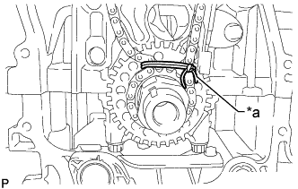
Text in Illustration *a String Tie the chain sub-assembly with a string above the crankshaft timing gear or sprocket to secure the chain sub-assembly.
-
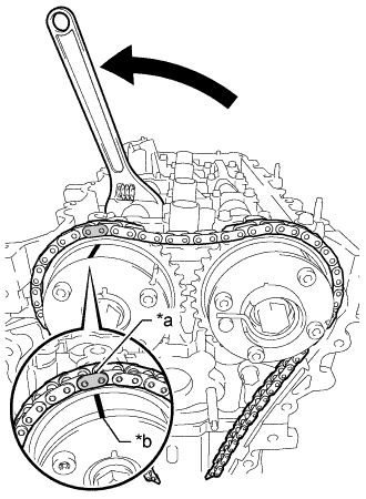
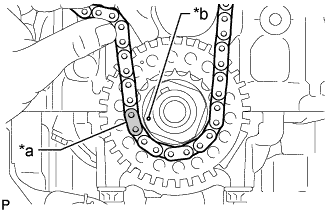
Text in Illustration *a Mark Plate (Orange) *b Timing Mark Using the hexagonal portion of the camshaft, rotate the camshaft counterclockwise with a wrench.
Align the timing mark of the camshaft timing gear assembly with the mark plate (orange) of the chain sub-assembly and install the chain sub-assembly to the camshaft timing gear assembly.
Tech Tips
Hold the camshaft in place with a wrench until the No. 1 chain tensioner assembly is installed.
-
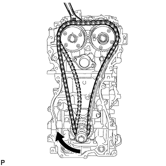
Remove the string above the crankshaft timing gear or sprocket, rotate the crankshaft clockwise, and loosen the chain sub-assembly so that the chain tensioner slipper can be installed.
Note
Make sure that the chain sub-assembly is securely installed.
-
-
INSTALL CHAIN TENSIONER SLIPPER
-
Install the chain tensioner slipper with the bolt.
- Torque:
- 21 N*m { 214 kgf*cm, 15 ft.*lbf }
-
-
INSTALL NO. 1 CHAIN TENSIONER ASSEMBLY
-
Install a new chain tensioner gasket and the No. 1 chain tensioner assembly with the 2 bolts.
- Torque:
- 10 N*m { 102 kgf*cm, 7 ft.*lbf }
-
Remove the pin from the stopper plate.
-
Text in Illustration *a Lock Pin Released *b Lock Pin Locked *c Pin Hole *d Lock Check Point Rotate the camshaft counterclockwise, and then check that the camshaft timing gear assembly locks at the most retarded position.
Note
If the camshaft timing gear assembly is not locked, make sure to lock it securely.
-
-
INSTALL TIMING CHAIN GUIDE
-
Install the timing chain guide with the bolt.
- Torque:
- 21 N*m { 214 kgf*cm, 15 ft.*lbf }
-
-
CHECK NO. 1 CYLINDER TO TDC/COMPRESSION
-
Temporarily install the crankshaft pulley set bolt.
-
Rotate the crankshaft clockwise so that the timing marks on the crankshaft timing gear or sprocket and camshaft timing gears are positioned as shown in the illustration.
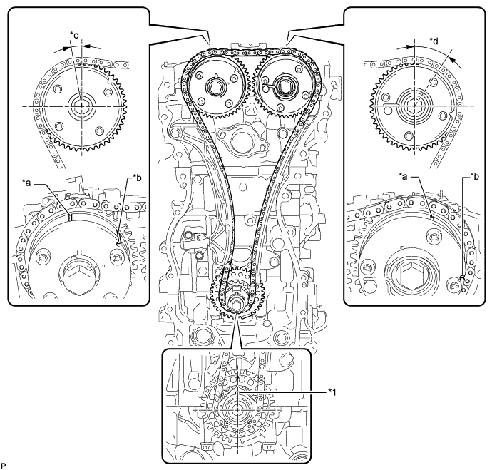
Text in Illustration *1 Crankshaft Pulley Set Crankshaft Key - - *a Timing Mark *b Identification Groove *c Approximately 7° *d Approximately 32° Tech Tips
-
The camshaft timing gear assembly and the camshaft timing exhaust gear assembly have both timing marks and identification grooves. Use the timing marks for alignment.
-
If the timing marks do not align, rotate the crankshaft clockwise again and align the timing marks.
-
-
Remove the crankshaft pulley set bolt.
-
-
INSTALL TIMING CHAIN COVER PLATE
-
Install a new No. 1 timing belt cover gasket and the timing chain cover plate with the 4 bolts.
- Torque:
- 10 N*m { 102 kgf*cm, 7 ft.*lbf }
-
-
INSTALL TIMING CHAIN COVER ASSEMBLY
-
Remove any old packing (FIPG material) and be careful not to drop any oil on the contact surfaces of the timing chain cover assembly, camshaft housing sub-assembly, stiffening crankcase assembly, cylinder block sub-assembly and cylinder head sub-assembly.
Note
Be sure to clean and degrease the contact surfaces, especially the surfaces indicated in the illustration.
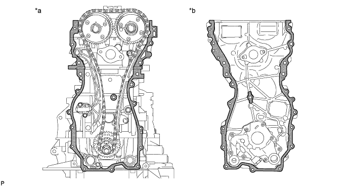
Text in Illustration *a Engine Side *b Timing Chain Cover Assembly Side Clean and degrease - - -
Apply a light coat of engine oil to 2 new gaskets.
-
Install the 2 gaskets to the stiffening crankcase assembly and oil strainer sub-assembly.
-
Install a water outlet gasket to the cylinder head sub-assembly.
-
Text in Illustration *1 Oil Pump Drive Rotor Spline *2 Crankshaft Timing Sprocket Align the oil pump drive rotor spline and crankshaft timing sprocket as shown in the illustration.
-
Apply seal packing as shown in the illustration.
Seal packing Toyota Genuine Seal Packing Black, Three Bond 1207B or equivalent Note
-
Install the timing chain cover assembly within 3 minutes and tighten the bolts and nuts within 10 minutes after applying seal packing.
-
Do not add engine oil within 2 hours of installation.
-
Do not start the engine for at least 2 hours after the installation.
Application Specification Area Seal Packing Diameter Seal Packing Width Seal Packing Height Application Position from Inside Seal Line Dashed line area 3.0 mm (0.118 in.) - - 2.5 mm (0.0984 in.) A - A 3.0 mm (0.118 in.) - - 2.5 mm (0.0984 in.) B - B 5.0 mm (0.197 in.) 7.0 mm (0.276 in.) or more 3.0 mm (0.118 in.) or more 3.0 mm (0.118 in.) C - C 7.0 mm (0.276 in.) 13 mm (0.512 in.) or more 3.0 mm (0.118 in.) or more 5.0 mm (0.197 in.) D - D 5.0 mm (0.197 in.) 7.0 mm (0.276 in.) or more 3.0 mm (0.118 in.) or more 3.0 mm (0.118 in.) E 3.0 mm (0.118 in.) - - 3.0 mm (0.118 in.) 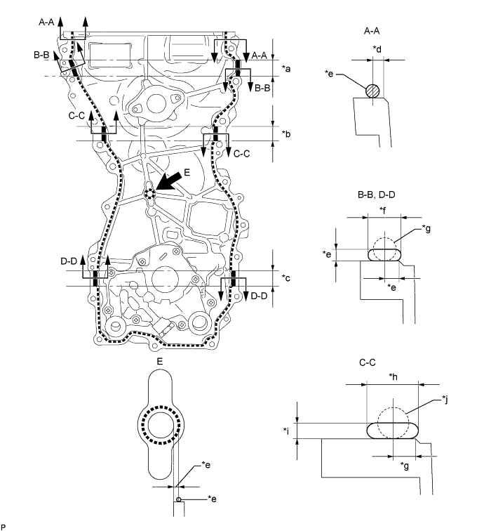
Text in Illustration *a 28 mm (1.102 in.) *b 25 mm (0.984 in.) *c 26 mm (1.024 in.) *d 2.5 mm (0.0984 in.) *e 3.0 mm (0.118 in.) *f 7.0 mm (0.276 in.) or more *g 5.0 mm (0.197 in.) *h 13 mm (0.512 in.) or more *i 3.0 mm (0.118 in.) or more *j 7.0 mm (0.276 in.) -
-
Temporarily install the timing chain cover assembly with the 19 bolts (A, B and C) and 2 nuts.
Standard Bolt Item Length Bolt Diameter Bolt A 30 mm (1.18 in.) 8.0 mm (0.315 in.) Bolt B 35 mm (1.38 in.) 10 mm (0.394 in.) Bolt C 45 mm (1.77 in.) 8.0 mm (0.315 in.) Note
Make sure that there is no oil on the threads of bolt B.
-
Tighten the 19 bolts and 3 nuts in the order shown in the illustration.
- Torque:
- Bolt A, C and Nut
- 21 N*m { 214 kgf*cm, 15 ft.*lbf }
- Bolt B
- 55 N*m { 561 kgf*cm, 41 ft.*lbf }
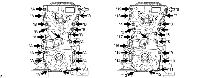
Text in Illustration Bolt Nut
-
-
INSTALL TIMING GEAR CASE OR TIMING CHAIN CASE OIL SEAL
-
Apply MP grease to the lip of a new timing gear case or timing chain case oil seal.
Note
-
Keep the lip free from foreign matter.
-
Do not allow MP grease to contact the dust seal.
-
-
Text in Illustration *a Depth Using SST and a hammer, tap in the timing gear case or timing chain case oil seal until its surface is flush with the timing chain cover assembly edge.
- SST
- 09636-20010
Standard depth 0.75 to 1.45 mm (0.0295 to 0.0571 in.) Note
-
Do not tap in the timing gear case or timing chain case oil seal at an angle.
-
Keep the lip free from foreign matter.
-
Wipe off any MP grease from the crankshaft.
-
-
INSTALL CRANKSHAFT PULLEY ASSEMBLY
-
Align the crankshaft pulley set crankshaft key with the key groove of the crankshaft pulley assembly.
-
Text in Illustration *a Hold *b Turn Using SST, hold the crankshaft pulley assembly and install the crankshaft pulley set bolt.
- SST
- 09213-54015
- 09330-00021
- Torque:
- 260 N*m { 2651 kgf*cm, 192 ft.*lbf }
Tech Tips
SST (Crankshaft pulley holding tool) fixing bolt part No.: 91551-80650 (2 pcs)
-
-
INSTALL CRANKSHAFT POSITION SENSOR
-
Apply a light coat of engine oil to the O-ring of the crankshaft position sensor.
-
Install the crankshaft position sensor to the timing chain cover assembly with a new bolt.
- Torque:
- 6.5 N*m { 66 kgf*cm, 58 in.*lbf }
Note
-
If a crankshaft position sensor has been struck or dropped, replace it.
-
Make sure that the O-ring is not cracked or moved out of place during installation.
-
Connect the crankshaft position sensor connector.
-
-
INSTALL SPARK PLUG TUBE GASKET
-
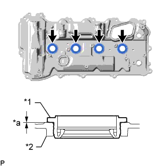
Text in Illustration *1 Spark Plug Tube Gasket *2 Cylinder Head Cover Sub-assembly *a 0 mm (0 in.) Install 4 new spark plug tube gaskets to the cylinder head cover sub-assembly as shown in the illustration.
Note
-
Do not allow foreign matter to contact the lip of the spark plug tube gasket.
-
Do not tap in the spark plug tube gasket at an angle.
-
-
-
INSTALL PCV CASE SUB-ASSEMBLY
-
Apply a light coat of engine oil to a new O-ring.
-
Text in Illustration *1 O-ring *a O-ring Groove Install the O-ring to the PCV case sub-assembly as shown in the illustration.
Note
Securely install the O-ring to the O-ring groove of the PCV case sub-assembly.
-
Install the PCV case sub-assembly to the cylinder head cover sub-assembly with the 2 bolts.
- Torque:
- 10 N*m { 102 kgf*cm, 7 ft.*lbf }
-
Install a new gasket to the PCV case sub-assembly.
-
-
INSTALL CYLINDER HEAD COVER SUB-ASSEMBLY
-
Apply a light coat of engine oil to 3 new gaskets.
-
Install the 3 gaskets to the camshaft bearing caps.
-
Install a new cylinder head cover gasket to the cylinder head cover sub-assembly.
-
Text in Illustration *1 Timing Chain Cover Assembly *2 Camshaft Housing Sub-assembly *a 5.0 mm (0.197 in.) Seal Packing Apply seal packing as shown in the illustration.
Seal packing Toyota Genuine Seal Packing Black, Three Bond 1207B or equivalent Standard seal diameter 3.0 to 6.0 mm (0.118 to 0.236 in.) Note
-
Be sure to clean and degrease the contact surfaces.
-
Install the cylinder head cover sub-assembly within 3 minutes and tighten the bolts within 15 minutes after applying seal packing.
-
Do not add engine oil within 2 hours of installation.
-
Do not start the engine for at least 2 hours after the installation.
-
-
Text in Illustration *a Pin A *b Pin B Bolt A Bolt B Align the pin holes in the cylinder head cover sub-assembly with pin A and pin B in this order, and then install the cylinder head cover sub-assembly.
-
Temporarily install 3 new seal washers and the 3 bolts labeled B.
-
Temporarily install the 13 bolts labeled A.
-
Tighten the 16 bolts in the order shown in the illustration.
- Torque:
- 12 N*m { 122 kgf*cm, 9 ft.*lbf }
Standard Bolt Item Length Bolt A 25 mm (0.984 in.) Bolt B 35 mm (1.38 in.)
-
-
INSTALL OIL FILLER CAP GASKET
-
Install the oil filler cap gasket to the oil filler cap sub-assembly.
-
-
INSTALL OIL FILLER CAP SUB-ASSEMBLY
-
Install the oil filler cap sub-assembly to the cylinder head cover sub-assembly.
-
-
INSTALL PCV VALVE SUB-ASSEMBLY
-
Degrease the threaded portion of the PCV valve sub-assembly.
-
Apply adhesive 1324 to the PCV valve sub-assembly.
Adhesive Toyota Genuine Adhesive 1324, Three Bond 1324 or equivalent Note
Install the PCV valve sub-assembly within 3 minutes of applying adhesive.
-
Using a 19 mm deep socket wrench, install the PCV valve sub-assembly.
- Torque:
- 27 N*m { 275 kgf*cm, 20 ft.*lbf }
Note
Do not start the engine for at least 1 hour after the installation.
-
-
INSTALL VVT SENSOR
-
for Intake Side:
-
Apply a light coat of engine oil to the O-ring of the VVT sensor.
-
Install the VVT sensor to the cylinder head cover sub-assembly with a new bolt.
- Torque:
- 10 N*m { 102 kgf*cm, 7 ft.*lbf }
Note
-
Make sure that the O-ring is not cracked or moved out of place during installation.
-
If a VVT sensor has been struck or dropped, replace it.
-
Connect the VVT sensor connector.
-
-
for Exhaust Side:
-
Apply a light coat of engine oil to the O-ring of the VVT sensor.
-
Install the VVT sensor to the cylinder head cover sub-assembly with a new bolt.
- Torque:
- 10 N*m { 102 kgf*cm, 7 ft.*lbf }
Note
-
Make sure that the O-ring is not cracked or moved out of place during installation.
-
If a VVT sensor has been struck or dropped, replace it.
-
Connect the VVT sensor connector.
-
-
-
INSTALL CAMSHAFT TIMING OIL CONTROL VALVE ASSEMBLY
-
for Intake Side:
-
Apply a light coat of engine oil to a new O-ring and install it to the camshaft timing oil control valve assembly.
-
Install the camshaft timing oil control valve assembly to the cylinder head cover sub-assembly with the bolt.
- Torque:
- 10 N*m { 102 kgf*cm, 7 ft.*lbf }
Note
-
Do not allow foreign matter to contact the oil seal face of the camshaft timing oil control valve assembly (connecting surface with the cylinder head cover sub-assembly).
-
Make sure that the O-ring is not cracked or moved out of place when installing the camshaft timing oil control valve assembly.
-
Connect the camshaft timing oil control valve assembly connector.
-
-
for Exhaust Side:
-
Apply a light coat of engine oil to a new O-ring and install it to the camshaft timing oil control valve assembly.
-
Install the camshaft timing oil control valve assembly to the cylinder head cover sub-assembly with the bolt.
- Torque:
- 10 N*m { 102 kgf*cm, 7 ft.*lbf }
Note
-
Do not allow foreign matter to contact the oil seal face of the camshaft timing oil control valve assembly (connecting surface with the cylinder head cover sub-assembly).
-
Make sure that the O-ring is not cracked or moved out of place when installing the camshaft timing oil control valve assembly.
-
Connect the camshaft timing oil control valve assembly connector.
-
-
-
INSTALL ENGINE OIL PRESSURE SWITCH ASSEMBLY
-
Degrease the threaded portion of the oil pressure switch assembly.
-
Apply adhesive to 2 or 3 threads of the engine oil pressure switch assembly.
Adhesive Toyota Genuine Adhesive 1344, Three Bond 1344 or equivalent Note
-
Install the engine oil pressure switch assembly within 3 minutes after applying adhesive.
-
Do not apply adhesive to the oil inlet port of the engine oil pressure switch assembly.
-
-
Using a 24 mm deep socket wrench, install the engine oil pressure switch assembly.
- Torque:
- 15 N*m { 153 kgf*cm, 11 ft.*lbf }
Note
Do not start the engine within 1 hour of installation.
-
-
INSTALL KNOCK CONTROL SENSOR
-
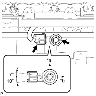
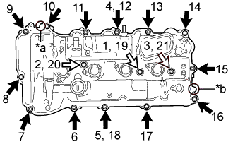
Text in Illustration *a Top *b Engine Front Install the knock control sensor to the cylinder block sub-assembly with the bolt as shown in the illustration.
- Torque:
- 20 N*m { 204 kgf*cm, 15 ft.*lbf }
Note
-
Make sure that the knock control sensor is in the correct position.
-
If a knock control sensor has been struck or dropped, replace it.
Tech Tips
Perform "Inspection After Repair" after replacing the knock control sensor.
-
w/ EGR System: Click here
-
w/o EGR System: Click here
-
Connect the knock control sensor connector.
-
-
INSTALL SPARK PLUG
-
Install the 4 spark plugs to the cylinder head sub-assembly.
- Torque:
- 25 N*m { 255 kgf*cm, 18 ft.*lbf }
Note
If a spark plug has been struck or dropped, replace it.
Tech Tips
-
Install the same parts to their original positions.
-
Perform "Inspection After Repair" after replacing a spark plug.
w/ EGR System: Click here
w/o EGR System: Click here
-
-
INSTALL NO. 4 WATER BY-PASS PIPE
-
Install the No. 4 water by-pass pipe with the 2 bolts.
- Torque:
- 10 N*m { 102 kgf*cm, 7 ft.*lbf }
-
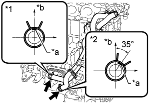
Text in Illustration *1 No. 7 Water By-pass Hose *2 No. 8 Water By-pass Hose *a Paint Mark *b Upper Side Connect the No. 7 water by-pass hose and No. 8 water by-pass hose to the oil cooler assembly with the 2 hose clamps as shown in the illustration.
-
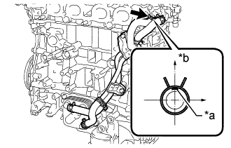
Text in Illustration *a Paint Mark *b Upper Side Connect the No. 9 water by-pass hose to the cylinder head sub-assembly with the hose clamp as shown in the illustration.
-