БЛОК ДВИГАТЕЛЯ РАЗБОРКА

-
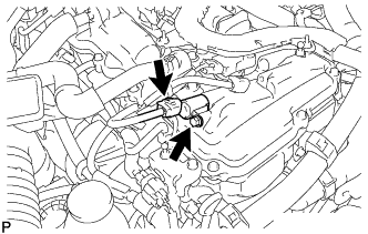
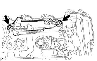
REMOVE NO. 4 WATER BY-PASS PIPE
-
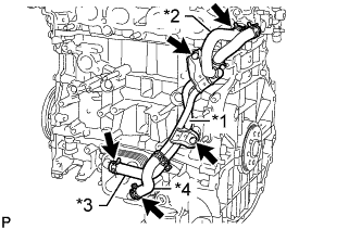
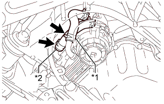
Text in Illustration *1 No. 4 Water By-pass Pipe *2 No. 9 Water By-pass Hose *3 No. 7 Water By-pass Hose *4 No. 8 Water By-pass Hose Slide the clip and disconnect the No. 9 water by-pass hose from the cylinder head sub-assembly.
-
Slide the 2 clips and disconnect the No. 7 water by-pass hose and No. 8 water by-pass hose from the oil cooler assembly.
-
Remove the 2 bolts and No. 4 water by-pass pipe.
-
-
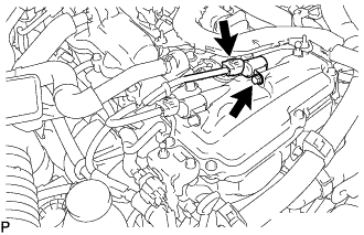
REMOVE SPARK PLUG
-
Remove the 4 spark plugs from the cylinder head sub-assembly.
Note
If a spark plug has been struck or dropped, replace it.
Tech Tips
Arrange the removed parts in the correct order.
-
-
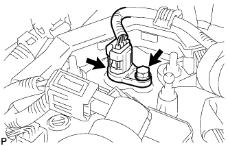
REMOVE KNOCK CONTROL SENSOR
-
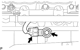
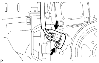
Disconnect the knock control sensor connector.
-
Remove the bolt and knock control sensor from the cylinder block sub-assembly.
-
-
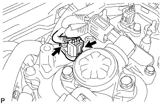
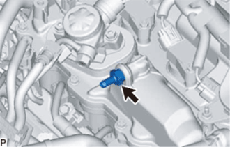
REMOVE ENGINE OIL PRESSURE SWITCH ASSEMBLY
-
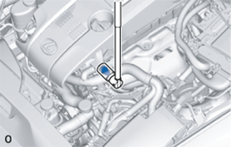
Disconnect the engine oil pressure switch assembly connector.
-
Using a 24 mm deep socket wrench, remove the engine oil pressure switch assembly.
-
-
REMOVE CAMSHAFT TIMING OIL CONTROL VALVE ASSEMBLY
-
for Exhaust Side:
-
Disconnect the camshaft timing oil control valve assembly connector.
-
Remove the bolt and camshaft timing oil control valve assembly from the cylinder head cover sub-assembly.
Note
Do not allow foreign matter to contact the oil seal face of the camshaft timing oil control valve assembly (connecting surface with the cylinder head cover sub-assembly).
-
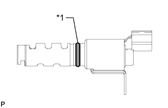
Text in Illustration *1 O-ring Remove the O-ring from the camshaft timing oil control valve assembly.
-
-
for Intake Side:
-
Disconnect the camshaft timing oil control valve assembly connector.
-
Remove the bolt and camshaft timing oil control valve assembly from the cylinder head cover sub-assembly.
Note
Do not allow foreign matter to contact the oil seal face of the camshaft timing oil control valve assembly (connecting surface with the cylinder head cover sub-assembly).
-
Text in Illustration *1 O-ring Remove the O-ring from the camshaft timing oil control valve assembly.
-
-
-
REMOVE VVT SENSOR
-
for Exhaust Side:
-
Disconnect the VVT sensor connector.
-
Remove the bolt and VVT sensor from the cylinder head cover sub-assembly.
-
-
for Intake Side:
-
Disconnect the VVT sensor connector.
-
Remove the bolt and VVT sensor from the cylinder head cover sub-assembly.
-
-
-
REMOVE PCV VALVE SUB-ASSEMBLY
-
Using a 19 mm deep socket wrench, remove the PCV valve sub-assembly.
-
-
REMOVE OIL FILLER CAP SUB-ASSEMBLY
-
Remove the oil filler cap sub-assembly from the cylinder head cover sub-assembly.
-
-
REMOVE OIL FILLER CAP GASKET
-
Remove the oil filler cap gasket from the oil filler cap sub-assembly.
-
-
REMOVE CYLINDER HEAD COVER SUB-ASSEMBLY
-
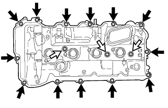
Remove the 16 bolts, 3 seal washers and cylinder head cover sub-assembly from the camshaft housing sub-assembly.
Text in Illustration 
Bolt 
Bolt with Seal Washer -
Remove the cylinder head cover gasket from the cylinder head cover sub-assembly.
-
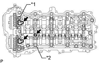
Text in Illustration *1 No. 1 Camshaft Bearing Cap *2 No. 2 Camshaft Bearing Cap Remove the 3 gaskets from the No. 1 camshaft bearing cap and No. 2 camshaft bearing cap.
-
-
REMOVE PCV CASE SUB-ASSEMBLY
-
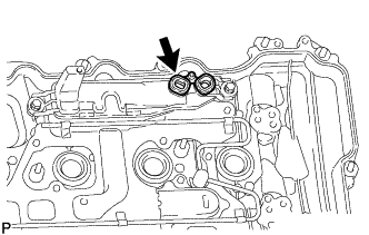
Remove the gasket from the PCV case sub-assembly.
-
Remove the 2 bolts and PCV case sub-assembly from the cylinder head cover sub-assembly.
-
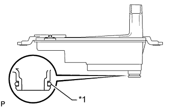
Text in Illustration *1 O-ring Remove the O-ring from the PCV case sub-assembly.
-
-
REMOVE SPARK PLUG TUBE GASKET
-
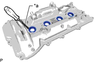
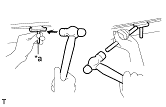
Text in Illustration *a Protective Tape Using a screwdriver, pry out the 4 spark plug tube gaskets.
Note
Be careful not to damage the cylinder head cover sub-assembly.
Tech Tips
Tape the screwdriver tip before use.
-
-
REMOVE CRANKSHAFT POSITION SENSOR
-
Disconnect the crankshaft position sensor connector.
-
Remove the bolt and crankshaft position sensor from the timing chain cover assembly.
-
-
REMOVE CRANKSHAFT PULLEY ASSEMBLY
-
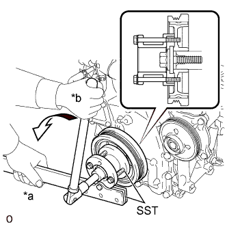
Text in Illustration *a Hold *b Turn Using SST, hold the crankshaft pulley assembly and loosen the crankshaft pulley set bolt. Further loosen the crankshaft pulley set bolt until 2 or 3 threads are screwed into the crankshaft.
- SST
- 09213-54015
- 09330-00021
Tech Tips
SST (Crankshaft pulley holding tool) fixing bolt part No.: 91551-80650 (2 pcs)
-
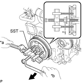
Text in Illustration *1 Crankshaft Pulley Set Bolt *a Hold *b Turn Using SST, remove the crankshaft pulley and crankshaft pulley set bolt.
- SST
- 09950-50013 ( 09951-05010, 09952-05010, 09953-05020, 09954-05011 )
Tech Tips
Apply molybdenum grease to the threads and tip of SST (center bolt) prior to use.
-
-
REMOVE TIMING CHAIN COVER ASSEMBLY
-
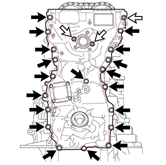
Remove the 19 bolts and 3 nuts from the timing chain cover assembly.
Text in Illustration Bolt Nut -
Remove the timing chain cover assembly by prying between the timing chain cover assembly and camshaft housing sub-assembly, stiffening crankcase assembly, cylinder block sub-assembly or cylinder head sub-assembly with a screwdriver.
Note
Be careful not to damage the contact surfaces of the timing chain cover assembly, camshaft housing sub-assembly, stiffening crankcase assembly, cylinder block sub-assembly and cylinder head sub-assembly.
Tech Tips
Tape the screwdriver tip before use.
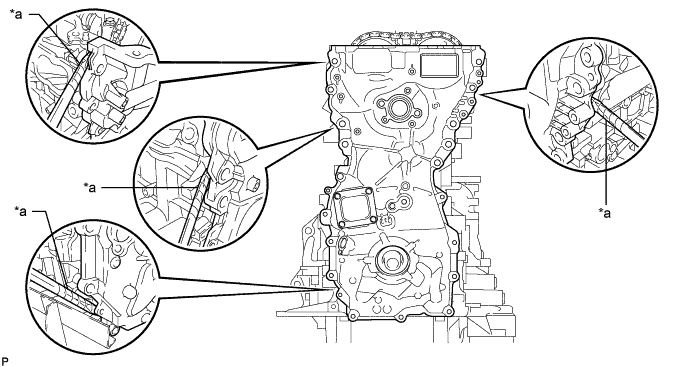
Text in Illustration *a Protective Tape - - -
Remove the gasket from the cylinder head sub-assembly.
-
Remove the 2 gaskets from the stiffening crankcase assembly and oil strainer sub-assembly.
-
-
REMOVE TIMING CHAIN COVER PLATE
-
Remove the 4 bolts, timing chain cover plate and No. 1 timing belt cover gasket from the timing chain cover assembly.
-
-
REMOVE TIMING GEAR CASE OR TIMING CHAIN CASE OIL SEAL
-
Text in Illustration *a Protective Tape *b Wooden Block Using a screwdriver and wooden block, pry out the timing gear case or timing chain case oil seal.
Note
Do not damage the surface of the timing gear case or timing chain case oil seal press fit hole.
Tech Tips
Tape the screwdriver tip before use.
-
-
SET NO. 1 CYLINDER TO TDC/COMPRESSION
-
Temporarily install the crankshaft pulley set bolt.
-
Rotate the crankshaft clockwise so that the timing marks on the crankshaft timing gear or sprocket and camshaft timing gears are positioned as shown in the illustration.
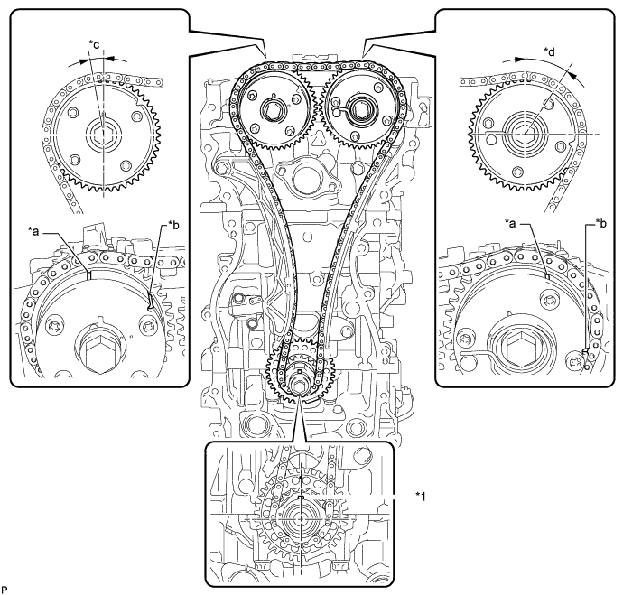
Text in Illustration *1 Crankshaft Pulley Set Crankshaft Key - - *a Timing Mark *b Identification Groove *c Approximately 7° *d Approximately 32° Tech Tips
-
The camshaft timing gear assembly and the camshaft timing exhaust gear assembly have both timing marks and identification grooves. Use the timing marks for alignment.
-
If the timing marks do not align, rotate the crankshaft clockwise again and align the timing marks.
-
-
Remove the crankshaft pulley set bolt.
-
-
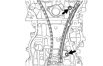
REMOVE TIMING CHAIN GUIDE
-
Remove the bolt and timing chain guide.
-
-
REMOVE NO. 1 CHAIN TENSIONER ASSEMBLY
-
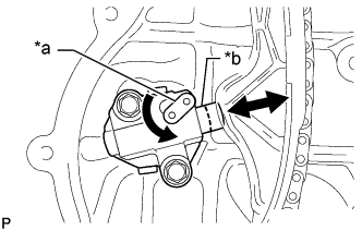
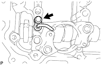
Text in Illustration *a Stopper Plate *b Plunger Allow the plunger to extend slightly, and then rotate the stopper plate counterclockwise to release the lock. Once the lock is released, push the plunger into the tensioner.
-
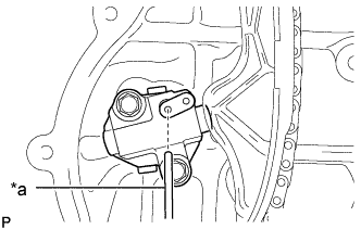
Text in Illustration *a Pin Move the stopper plate clockwise to set the lock, and insert a pin into the stopper plate hole.
-
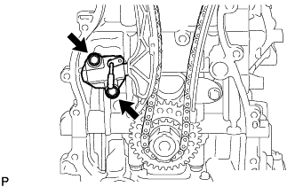
Remove the 2 bolts, No. 1 chain tensioner assembly and chain tensioner gasket.
-
-
REMOVE CHAIN TENSIONER SLIPPER
-
Remove the bolt and chain tensioner slipper.
-
-
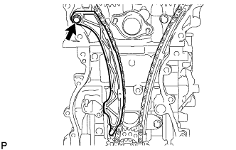
REMOVE NO. 1 CHAIN VIBRATION DAMPER
-
Remove the 2 bolts and No. 1 chain vibration damper.
-
-
REMOVE CHAIN SUB-ASSEMBLY
-
Remove the chain sub-assembly.
-
-
REMOVE CRANKSHAFT TIMING GEAR OR SPROCKET
-
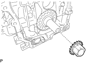
Remove the crankshaft timing gear or sprocket from the crankshaft.
-
-
REMOVE CRANKSHAFT PULLEY SET CRANKSHAFT KEY
-
Text in Illustration *a Protective Tape Using a screwdriver, remove the 2 crankshaft pulley set crankshaft keys from the crankshaft.
Tech Tips
Tape the screwdriver tip before use.
-
-
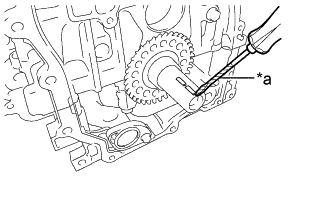
REMOVE CAMSHAFT TIMING GEAR ASSEMBLY
-
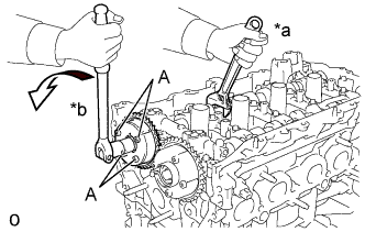
Text in Illustration *a Hold *b Turn Hold the hexagonal portion of the camshaft with a wrench and remove the bolt and camshaft timing gear assembly.
Note
-
Never remove the 4 bolts (A). If they are removed, make sure to replace the camshaft timing gear assembly.
-
Be careful not to damage the camshaft housing sub-assembly or spark plug tube with the wrench.
-
-
Remove the camshaft timing gear assembly from the camshaft.
-
-
REMOVE CAMSHAFT TIMING EXHAUST GEAR ASSEMBLY
-
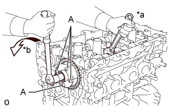
Text in Illustration *a Hold *b Turn Hold the hexagonal portion of the No. 2 camshaft with a wrench and remove the bolt and camshaft timing exhaust gear assembly.
Note
-
Never remove the 4 bolts (A). If they are removed, make sure to replace the camshaft timing exhaust gear assembly.
-
Be careful not to damage the camshaft housing sub-assembly or spark plug tube with the wrench.
-
-
Remove the camshaft timing exhaust gear assembly from the No. 2 camshaft.
-
-
REMOVE OIL PIPE SUB-ASSEMBLY
-
Remove the bolt and oil pipe sub-assembly from the No. 4 camshaft bearing cap.
-
-
REMOVE CAMSHAFT HOUSING SUB-ASSEMBLY
-
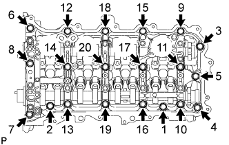
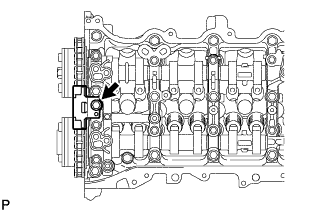
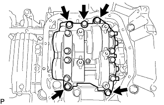
Uniformly loosen and remove the 20 bolts in the sequence shown in the illustration.
-
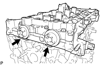
Remove the camshaft housing sub-assembly by prying between the cylinder head sub-assembly and camshaft housing sub-assembly with a screwdriver.
Note
Be careful not to damage the contact surfaces of the cylinder head sub-assembly and camshaft housing sub-assembly.
Tech Tips
Tape the screwdriver tip before use.
-
-
REMOVE CAMSHAFT BEARING CAP
-
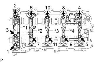
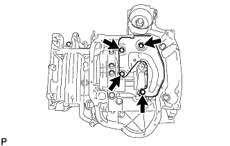
Text in Illustration *1 No. 1 Camshaft Bearing Cap *2 No. 2 Camshaft Bearing Cap *3 No. 3 Camshaft Bearing Cap *4 No. 4 Camshaft Bearing Cap Uniformly loosen and remove the 11 bolts in the sequence shown in the illustration.
-
Remove the No. 1 camshaft bearing cap, No. 2 camshaft bearing cap, No. 3 camshaft bearing cap and No. 4 camshaft bearing cap.
-
-
REMOVE OIL CONTROL VALVE FILTER
-
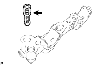
Remove the oil control valve filter from the No. 1 camshaft bearing cap.
Note
Do not touch the mesh section on the oil control valve filter.
-
-
REMOVE NO. 1 CAMSHAFT BEARING
-
Remove the No. 1 camshaft bearing from the No. 1 camshaft bearing cap.
-
-
REMOVE CAMSHAFT
-
Remove the camshaft from the camshaft housing sub-assembly.
-
-
REMOVE NO. 2 CAMSHAFT
-
Remove the No. 2 camshaft from the camshaft housing sub-assembly.
-
-
REMOVE NO. 2 CAMSHAFT BEARING
-
Remove the No. 2 camshaft bearing from the camshaft housing sub-assembly.
-
-
REMOVE NO. 1 VALVE ROCKER ARM SUB-ASSEMBLY
-
Remove the 16 No. 1 valve rocker arm sub-assemblies from the cylinder head sub-assembly.
Tech Tips
Be sure to keep the removed parts for each installation position separate.
-
-
REMOVE VALVE LASH ADJUSTER ASSEMBLY
-
Remove the 16 valve lash adjuster assemblies from the cylinder head sub-assembly.
Tech Tips
Be sure to keep the removed parts for each installation position separate.
-
-
REMOVE VALVE STEM CAP
-
Remove the 16 valve stem caps from the valve stem ends.
Tech Tips
Be sure to keep the removed parts for each installation position separate.
-
-
REMOVE CYLINDER HEAD SUB-ASSEMBLY
-
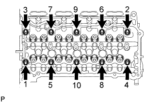
Using a 10 mm bi-hexagon wrench, uniformly loosen the 10 cylinder head set bolts in the sequence shown in the illustration. Remove the 10 cylinder head set bolts and plate washers.
Note
-
Be careful not to drop the plate washers into the cylinder head sub-assembly.
-
Cylinder head sub-assembly warpage or cracking could result from removing cylinder head set bolts in an incorrect order.
Tech Tips
Be sure to keep the removed parts for each installation position separate.
-
-
Remove the cylinder head sub-assembly.
-
-
REMOVE CYLINDER HEAD GASKET
-
Remove the cylinder head gasket from the cylinder block sub-assembly.
-
-
REMOVE CYLINDER BLOCK WATER JACKET SPACER
-
Remove the cylinder block water jacket spacer from the cylinder block sub-assembly.
Note
Be sure to remove the water jacket spacer. If it is not removed, it may fall and become damaged when the cylinder block sub-assembly is inverted.
-
-
REMOVE OIL FILTER CAP ASSEMBLY
-
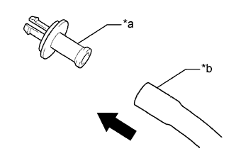
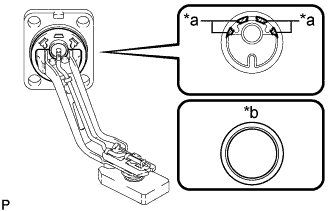
Text in Illustration *a Pipe *b Hose Connect a hose with an inside diameter of 15 mm (0.591 in.) to the pipe.
-
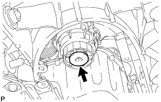
Remove the oil filter drain plug from the oil filter cap assembly.
-
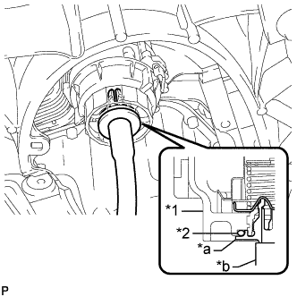
Text in Illustration *1 Oil Filter Cap Assembly *2 O-Ring *a Pipe *b Hose Insert the pipe with hose into the oil filter cap assembly.
Note
Be sure to insert the pipe with hose with the O-ring installed on the oil filter cap assembly.
Tech Tips
Place the hose end into a container before draining the engine oil from the hose.
-
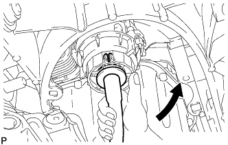
Make sure that the engine oil is completely drained, and remove the pipe with hose and O-ring.
Tech Tips
Be sure to turn the pipe in the direction of the arrow to remove it.
-
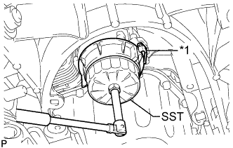
Text in Illustration *1 Oil Filter Bracket Clip Using SST, remove the oil filter cap assembly from the stiffening crankcase assembly.
- SST
- 09228-06501
Note
Do not remove the oil filter bracket clip when removing the oil filter cap assembly.
-
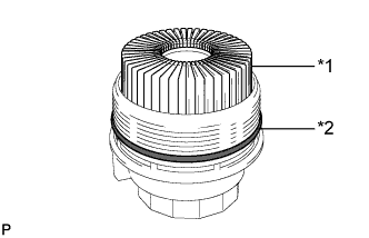
Text in Illustration *1 Oil Filter Element *2 O-Ring Remove the oil filter element and O-ring from the oil filter cap assembly.
Note
Do not use any tools to remove the O-ring to prevent damage to the oil filter cap assembly. Be sure to remove it by hand.
-
-
REMOVE ENGINE OIL LEVEL SENSOR
-
Disconnect the engine oil level sensor connector.
-
Remove the 4 bolts and engine oil level sensor.
-
Text in Illustration *a Cutting Position *b Supply Part Cut away part of the gasket and remove the gasket from the engine oil level sensor.
Tech Tips
Remove only the outer part of the gasket.
-
-
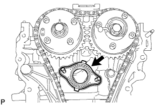
REMOVE OIL COOLER ASSEMBLY
-
Text in Illustration *1 No. 7 Water By-pass Hose *2 No. 8 Water By-pass Hose Slide the clamp and disconnect the No. 7 water by-pass hose from the oil cooler assembly.
Note
Spray lubricant agent between the oil cooler assembly pipe and No. 7 water by-pass hose so that the No. 7 water by-pass hose can be disconnected easily.
Tech Tips
Use a cloth to prevent lubricant agent from spattering.
-
Slide the clamp and disconnect the No. 8 water by-pass hose from the oil cooler assembly.
Note
Spray lubricant agent between the oil cooler assembly pipe and No. 8 water by-pass hose so that the No. 8 water by-pass hose can be disconnected easily.
Tech Tips
Use a cloth to prevent lubricant agent from spattering.
-
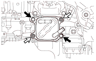
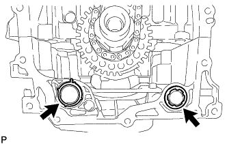
Remove the 2 nuts, 2 bolts and oil cooler assembly.
Text in Illustration Bolt Nut -
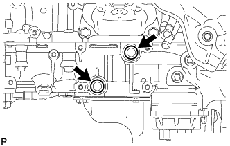
Remove the 2 O-rings from the stiffening crankcase assembly.
-
-
REMOVE OIL PAN DRAIN PLUG
-
Remove the oil pan drain plug and gasket from the oil pan sub-assembly.
-
-
REMOVE OIL PAN SUB-ASSEMBLY
-
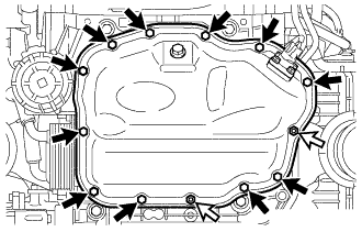
Remove the 11 bolts and 2 nuts.
Text in Illustration Bolt Nut -
Text in Illustration *a Oil Pan Seal Cutter Insert the blade of an oil pan seal cutter between the oil pan sub-assembly and stiffening crankcase assembly, cut off the applied sealer and remove the oil pan sub-assembly.
Note
-
Be careful not to damage the contact surface of the stiffening crankcase assembly and oil pan sub-assembly.
-
Be careful not to damage the oil pan sub-assembly flange.
Tech Tips
Be sure to clean the bolts and stud bolts and check the threads for cracks or other damage.
-
-
-
REMOVE OIL STRAINER SUB-ASSEMBLY
-
Remove the 3 bolts, oil strainer sub-assembly and gasket.
-
-
REMOVE NO. 1 OIL PAN BAFFLE PLATE
-
Remove the 4 bolts and No. 1 oil pan baffle plate.
-
-
REMOVE ENGINE BALANCER ASSEMBLY
-
Remove the 5 bolts and engine balancer assembly.
Note
Do not disassemble the engine balancer assembly.
-
-
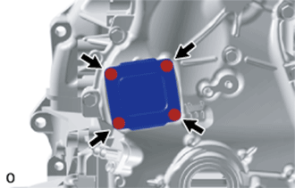
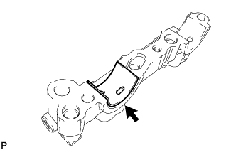
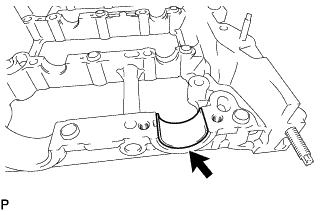
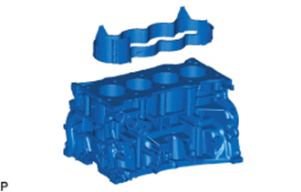
REMOVE STIFFENING CRANKCASE ASSEMBLY
-
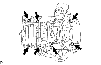
Remove the 7 bolts.
-
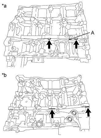
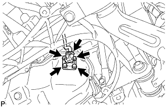
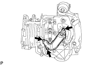
Text in Illustration *a LH Side *b RH Side Using a screwdriver, remove the stiffening crankcase assembly by prying between the stiffening crankcase assembly and cylinder block sub-assembly at the places shown in the illustration.
Note
-
Do not pry section A in the illustration. Otherwise, the stiffening case assembly may be damaged.
-
Be careful not to damage the contact surfaces of the cylinder block sub-assembly and stiffening crankcase assembly.
Tech Tips
Tape the screwdriver tip before use.
-
-
-
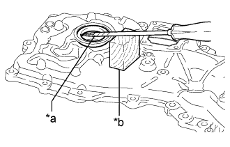
REMOVE REAR ENGINE OIL SEAL
-
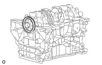
Remove the rear engine oil seal from the cylinder block sub-assembly.
-
-
REMOVE STUD BOLT
Note
If a stud bolt is deformed or its threads are damaged, replace it.
-
REMOVE CYLINDER HEAD SUB-ASSEMBLY
Note
If a ring pin is deformed or damaged, replace it.
-
REMOVE STRAIGHT PIN
Note
If a straight pin is deformed or damaged, replace it.