БЛОК ДВИГАТЕЛЯ СНЯТИЕ
-
REMOVE NO. 1 COMPRESSOR MOUNTING BRACKET
-
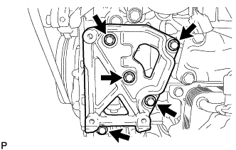
Remove the 5 bolts and No. 1 compressor mounting bracket.
-
-
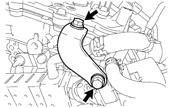
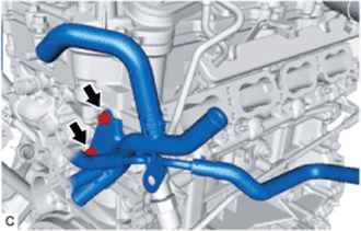
REMOVE NO. 1 WATER BY-PASS PIPE
-
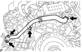
Slide the clip and disconnect the water by-pass hose from the No. 2 water by-pass pipe.
-
Remove the bolt, 2 nuts, No. 1 water by-pass pipe and gasket.
-
-
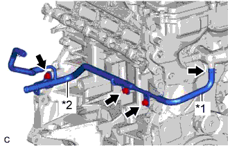
REMOVE WATER BY-PASS PIPE (w/o EGR System)
-
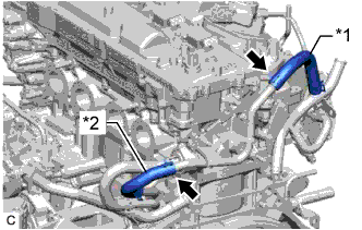
Text in Illustration *1 No. 5 Water By-pass Hose *2 No. 6 Water By-pass Hose Slide the 2 clips and disconnect the No. 5 water by-pass hose and No. 6 water by-pass hose from the water by-pass pipe.
-
Remove the bolt, nut and water by-pass pipe from the cylinder head sub-assembly.
-
-
DISCONNECT EGR VALVE BRACKET (w/ EGR System)
-
Remove the 2 bolts and EGR valve bracket from the EGR valve assembly and cylinder head sub-assembly.
-
-
REMOVE EGR COOLER ASSEMBLY (w/ EGR System)
-
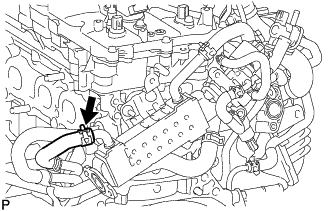
Slide the clip and disconnect the No. 6 water by-pass hose from the EGR cooler assembly.
-
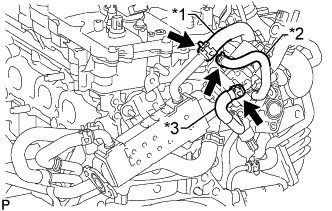
Text in Illustration *1 No. 5 Water By-pass Hose *2 No. 12 Water By-pass Hose *3 No. 4 Water By-pass Hose Slide the clip and disconnect the No. 5 water by-pass hose from the EGR cooler assembly.
-
Slide the clip and disconnect the No. 12 water by-pass hose from the EGR valve assembly.
-
Slide the clip and disconnect the No. 4 water by-pass hose from the EGR valve assembly.
-
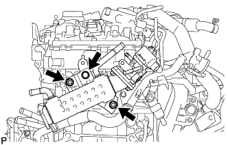
Remove the 2 nuts, bolt and EGR cooler assembly from the cylinder head sub-assembly.
-
-
REMOVE NO. 2 WATER BY-PASS PIPE
-
Remove the 2 bolts and No. 2 water by-pass pipe from the cylinder head sub-assembly.
-
-
REMOVE NO. 3 WATER BY-PASS PIPE
-
Slide the clip and disconnect the No. 13 water by-pass hose from the water outlet sub-assembly.
-
Remove the 3 bolts and No. 3 water by-pass pipe from the cylinder block sub-assembly.
-
-
REMOVE FRONT NO. 1 ENGINE MOUNTING BRACKET LH
-
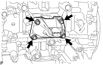
Remove the 4 bolts and front No. 1 engine mounting bracket LH from the cylinder block sub-assembly.
-
-
REMOVE FRONT NO. 1 ENGINE MOUNTING BRACKET RH
-
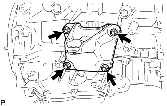
Remove the 4 bolts and front No. 1 engine mounting bracket RH from the cylinder block sub-assembly.
-
-
REMOVE IGNITION COIL ASSEMBLY
-
Disconnect the 4 ignition coil assembly connectors.
-
Remove the 3 nuts and disconnect the engine wire from the cylinder head cover sub-assembly.
-
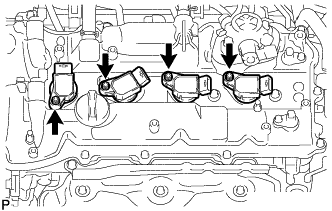
Remove the 4 bolts and 4 ignition coil assemblies from the cylinder head cover sub-assembly.
Note
If an ignition coil assembly has been struck or dropped, replace it.
Tech Tips
Arrange the removed parts in the correct order.
-
-
REMOVE ENGINE COVER JOINT
-
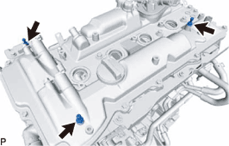
Remove the 3 engine cover joints.
-
-
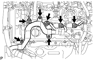
REMOVE WIRE HARNESS CLAMP BRACKET
-
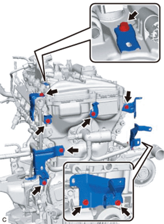
Remove the 9 bolts and 7 wire harness clamp brackets.
-
-
REMOVE ENGINE WATER PUMP ASSEMBLY
-
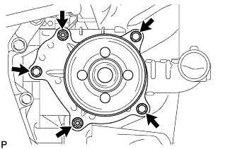
Remove the 3 bolts, 2 nuts and engine water pump assembly.
-
Remove the water pump gasket from the engine water pump assembly.
-
-
REMOVE WATER INLET WITH THERMOSTAT SUB-ASSEMBLY
-
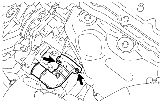
Remove the 2 nuts and water inlet with thermostat sub-assembly.
-
Remove the gasket from the water inlet with thermostat sub-assembly.
-
-
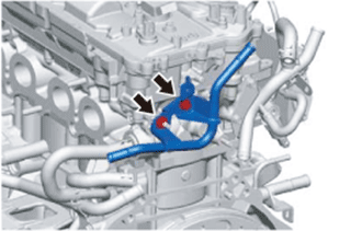
REMOVE NO. 5 WATER BY-PASS PIPE
-
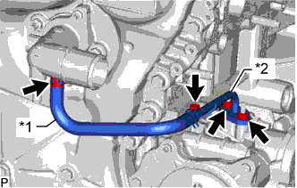
Text in Illustration *1 No. 11 Water By-pass Hose *2 No. 5 Water By-pass Pipe Slide the clip and disconnect the No. 11 water by-pass hose from the water outlet sub-assembly.
-
Remove the bolt, 2 nuts and No. 5 water by-pass pipe from the water inlet housing.
-
Remove the gasket from the water inlet housing.
-
-
REMOVE WATER INLET HOUSING
-
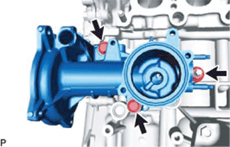
Remove the 2 bolts, nut and water inlet housing from the cylinder block sub-assembly.
-
Remove the gasket from the water inlet housing.
Note
If a stud bolt is deformed or its threads are damaged, replace it.
-
-
REMOVE NO. 1 FUEL PIPE
-
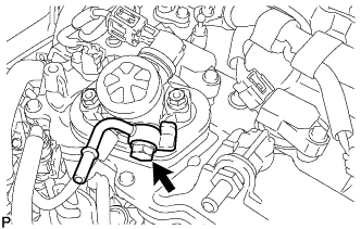
for Type A:
-
Remove the union bolt, No. 1 fuel pipe and 2 gaskets from the fuel pump with seal sub-assembly.
-
-
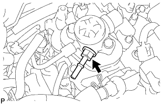
for Type B:
-
Using a 17 mm deep socket wrench, remove the No. 1 fuel pipe and gasket.
-
-
-
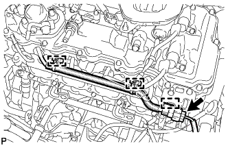
REMOVE NO. 1 FUEL PIPE SUB-ASSEMBLY
-
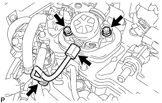
Using a 17 mm union nut wrench, loosen the 2 union nuts of the No. 1 fuel pipe sub-assembly.
-
Loosen the 2 bolts of the fuel pump with seal sub-assembly.
-
Remove the No. 1 fuel pipe sub-assembly.
-
-
REMOVE FUEL PUMP WITH SEAL SUB-ASSEMBLY
-
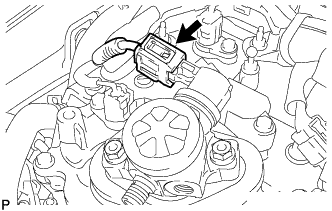
Disconnect the fuel pump with seal sub-assembly connector.
-
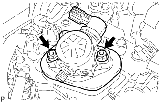
Remove the 2 bolts and fuel pump with seal sub-assembly.
-
Remove the fuel pump lifter assembly and fuel pump insulator from the fuel pump with seal sub-assembly.
-
Remove the O-ring from the fuel pump sub-assembly.
-
Remove the fuel pump spacer gasket from the cylinder head cover sub-assembly.
-
Remove the 2 O-rings from the pump housing of the cylinder head cover sub-assembly.
-
-
REMOVE FUEL DELIVERY PIPE
-
Disconnect the No. 6 engine wire connector.
-
Disconnect the 3 wire harness clamps from the fuel delivery pipe and wire harness clamp bracket.
-
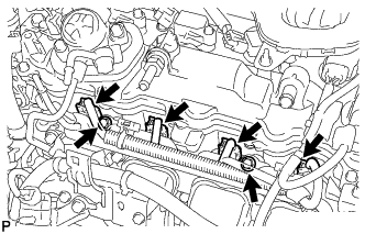
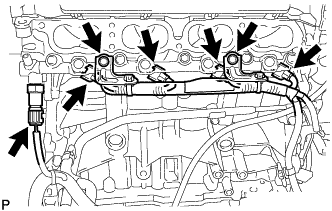
Disconnect the 4 fuel injector assembly connectors.
-
Remove the 2 bolts, and then remove the fuel delivery pipe together with the 4 fuel injector assemblies.
Note
Be careful not to drop the fuel injector assemblies when removing the fuel delivery pipe.
-
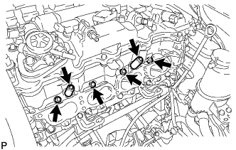
Remove the 2 No. 1 delivery pipe spacers from the cylinder head sub-assembly.
-
Remove the 4 injector vibration insulators from the cylinder head sub-assembly.
-
-
REMOVE FUEL INJECTOR ASSEMBLY
-
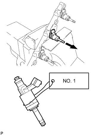
Remove the 4 fuel injector assemblies from the fuel delivery pipe.
Note
If the fuel injector assemblies are to be reused, reinstall them to the same cylinder they came from.
-
Remove the O-ring from each fuel injector assembly.
-
For reinstallation, attach a tag or label with the corresponding cylinder number to each fuel injector assembly.
Note
Protect the fuel injector assemblies by covering them with plastic bags.
-
-
REMOVE FUEL DELIVERY PIPE SUB-ASSEMBLY
-
Remove the 2 bolts and disconnect the wire harness from the fuel delivery pipe sub-assembly.
-
Disconnect the 4 fuel injector set connectors.
-
Disconnect the fuel pressure sensor connector.
Note
Do not pull the wire harness of the fuel pressure sensor excessively.
-
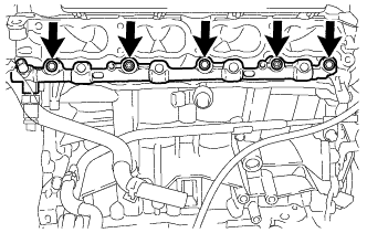
Remove the 3 bolts and 2 nuts, and then remove the fuel delivery pipe sub-assembly together with the 4 fuel injector sets.
Note
-
Be extremely careful not to touch or strike the tips of the fuel injector sets.
-
Be careful not to drop the fuel injector sets when removing the fuel delivery pipe sub-assembly.
-
-
-
REMOVE FUEL INJECTOR SET
-
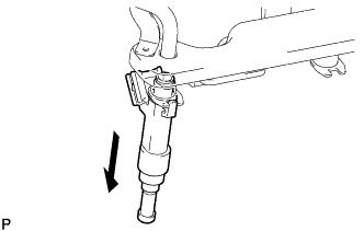
Secure the fuel delivery pipe sub-assembly in a vise between aluminum plates and pull out the 4 fuel injector sets.
Note
-
Pull and remove each fuel injector set in a straight line to avoid damage to the fuel injector seal surface of the fuel delivery pipe sub-assembly O-ring.
-
For reinstallation, attach a tag or label with the corresponding cylinder number to each fuel injector set.
-
-
Remove the nozzle holder clamp from each fuel injector set.
-
Using needle nose pliers, remove the No. 3 fuel injector back-up ring from each fuel injector set.
Note
Do not damage the part contacting the O-ring.
-
Remove the O-ring and No. 1 fuel injector back-up ring from each fuel injector set.
-
Remove the C-ring and injector vibration insulator from each fuel injector set.
-
-
REMOVE FUEL INJECTOR SEAL
-
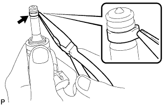
Using the tip of needle nose pliers, pinch and pull one of the fuel injector seals at several points to stretch it. Repeat this for the other fuel injector seals.
Note
-
Excessively pinching the fuel injector seal may damage the groove of the fuel injector set.
-
If a fuel injector set is dropped or the tip of a fuel injector set is struck, replace it with a new one.
-
-
Remove the fuel injector seal from the fuel injector set.
-
-
REMOVE ENGINE COOLANT TEMPERATURE SENSOR
-
Disconnect the engine coolant temperature sensor connector.
-
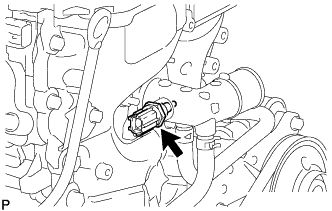
Using a 19 mm ball joint lock nut wrench, remove the engine coolant temperature sensor from the water outlet sub-assembly.
-
Remove the gasket from the engine coolant temperature sensor.
-
-
REMOVE WATER OUTLET SUB-ASSEMBLY
-
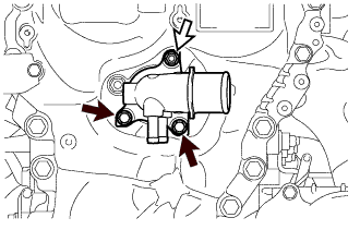
Remove the 2 bolts, nut and water outlet sub-assembly from the timing chain cover assembly.
Text in Illustration 
Bolt 
Nut -
Remove the O-ring from the timing chain cover assembly.
-