ЖГУТ ЭЛЕКТРОПРОВОДКИ РАМЫ СНЯТИЕ
-
PRECAUTION
CAUTION:
Be sure to read Precaution thoroughly before servicing Click here.
Note
After turning the power switch off, waiting time may be required before disconnecting the cable from the battery terminal. Therefore, make sure to read the disconnecting the cable from the battery terminal notice before proceeding with work Click here.
-
REMOVE LUGGAGE COMPARTMENT FLOOR MAT
-
Снимите напольный коврик багажного отделения.
-
-
REMOVE LUGGAGE COMPARTMENT TRIM COVER LH
-
Снимите левую облицовочную накладку багажного отделения.
-
-
DISCONNECT CABLE FROM AUXILIARY NEGATIVE BATTERY TERMINAL
Note
When disconnecting the cable, some systems need to be initialized after the cable is reconnected Click here.
Tech Tips
Both cables should be disconnected to prevent the AMD terminal from shorting to ground.
-
REMOVE SERVICE PLUG GRIP
-
REMOVE ENGINE ASSEMBLY WITH TRANSMISSION
-
REMOVE FUEL TANK ASSEMBLY
-
REMOVE REAR SEAT ASSEMBLY
-
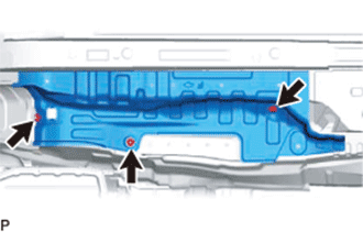
REMOVE NO. 4 FRONT FLOOR HEAT INSULATOR
-
Remove the 2 bolts and No. 4 front floor heat insulator.
-
-
REMOVE NO. 6 FRONT FLOOR HEAT INSULATOR
-
Remove the 3 nuts and No. 6 front floor heat insulator.
-
-
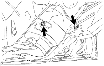
REMOVE NO. 13 WIRE HARNESS PROTECTOR
-
Detach the 2 clamps and remove the No. 13 wire harness protector.
-
-
REMOVE NO. 14 WIRE HARNESS PROTECTOR
-
Detach the clamp and remove the nut and No. 14 wire harness protector.
-
-
REMOVE AUXILIARY BATTERY TERMINAL
-
Remove the terminal cover and nut.
-
Remove the grommet and push the No. 4 floor wire out from the floor panel.
-
-
REMOVE NO. 4 HYBRID VEHICLE BATTERY SHIELD SUB-ASSEMBLY
CAUTION:
Wear insulated gloves.
-
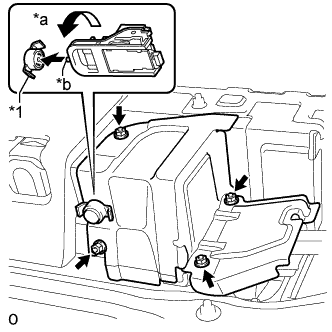
Remove the 2 clips and No. 1 hybrid battery intake duct LH.
-
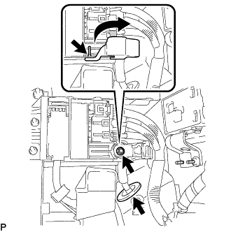
Text in Illustration *1 Battery Cover Lock Striker *a Turn *b Protrusion Using the service plug grip, remove the battery cover lock striker.
Tech Tips
Insert the protrusion of the service plug grip, and turn the button of the battery cover lock striker counterclockwise to release the lock.
-
Using an insulated tool, remove the 4 nuts and No. 4 hybrid vehicle battery shield sub-assembly.
-
-
REMOVE NO. 4 FLOOR WIRE
CAUTION:
Wear insulated gloves.
-
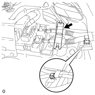
Remove the battery shield contact.
-
Detach the wire harness clamp.
-
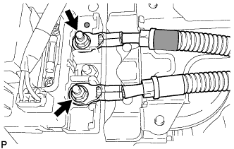
Using an insulated tool, remove the 2 nuts and disconnect the No. 4 floor wire.
Note
Insulate the removed terminals with insulating tape.
-
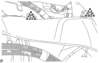
Detach the 2 wire harness clamps.
-
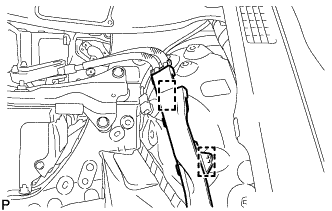
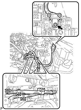
Remove the bolt and connector cover assembly.
Tech Tips
-
Make sure to pull the connector cover assembly straight up, as a connector is connected to the bottom of the connector cover assembly.
-
Do not allow any foreign objects or water to enter the inverter with converter assembly.
-
-
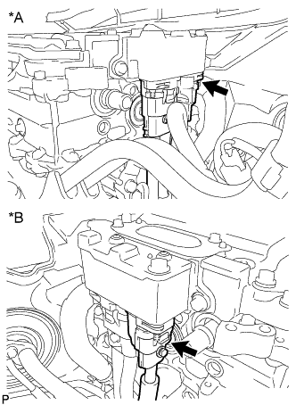
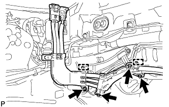
Text in Illustration *A for LHD *B for RHD Disconnect the air conditioning harness.
Note
-
Do not damage the terminals, connector housings or inverter with converter assembly when disconnecting them.
-
Do not touch the connector waterproofing rubber or terminals.
-
Insulate the removed terminals with insulating tape.
-
Do not allow any foreign objects or water to enter the inverter with converter assembly.
-
-
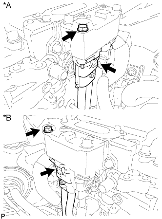
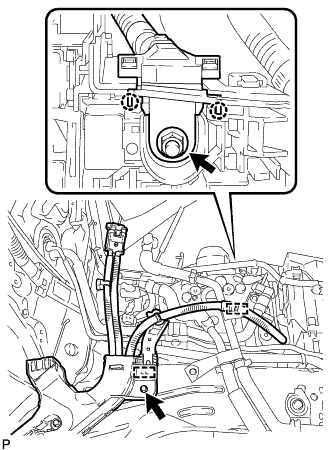
Text in Illustration *A for LHD *B for RHD Using an insulated tool, remove the bolt and disconnect the No. 4 floor wire.
Note
-
Do not damage the terminals, connector housings or inverter with converter assembly when disconnecting them.
-
Do not touch the connector waterproofing rubber or terminals.
-
Insulate the removed terminals with insulating tape.
-
Do not allow any foreign objects or water to enter the inverter with converter assembly.
-
-
Temporarily install the connector cover assembly with the bolt to prevent any foreign objects or water from entering the inverter with converter assembly.
-
for LHD:
-
Remove the 4 nuts and detach the 2 wire harness clamps.
-
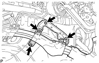
Remove the 2 bolts and 2 nuts, and detach the wire harness clamp.
-
Detach the 4 wire harness clamps.
-
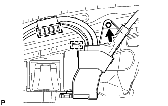
Remove the nut and detach the 2 claws.
-
-
for RHD:
-
Remove the bolt and detach the 2 wire harness clamps.
-
Remove the nut and detach the 2 claws.
-
-
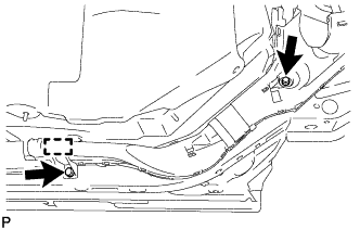
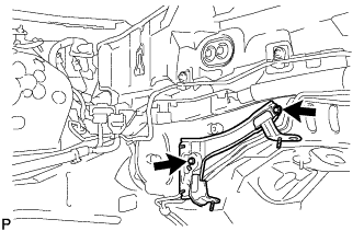
Remove the 2 bolts and detach the clamp.
-
Remove the bolt and detach the 2 clamps.
-
Remove the bolt.
-
Detach the 2 wire harness clamps.
-
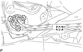
Detach the 3 claws and clamp, and push the frame wire out from the floor panel.
-
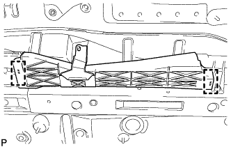
for LHD:
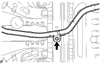
Disconnect the 5 stud clamps and remove the No. 4 floor wire.
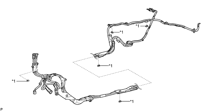
Text in Illustration *1 Stud Clamp - - Tech Tips
When removing the stud clamp, break the claw on the stud clamp. The stud clamp cannot be reused.
-
for RHD:
Disconnect the 4 stud clamps and remove the No. 4 floor wire.
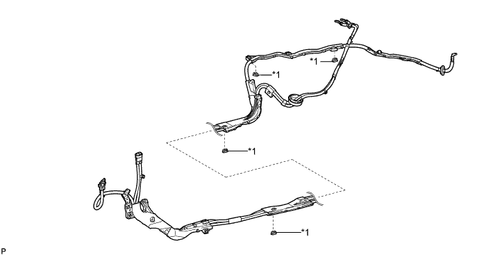
Text in Illustration *1 Stud Clamp - - Tech Tips
When removing the stud clamp, break the claw on the stud clamp. The stud clamp cannot be reused.
-
-
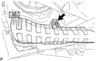
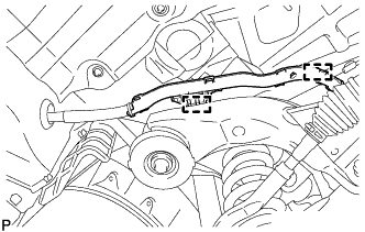
REMOVE WIRE HARNESS CLAMP BRACKET B (for LHD)
-
Remove the 2 bolts and wire harness clamp bracket B.
-