ВЫСОКОВОЛЬТНАЯ АККУМУЛЯТОРНАЯ БАТАРЕЯ ЗАРЯДКА

-
PRECAUTION
CAUTION:
Be sure to read Precaution thoroughly before servicing Click here.
-
INSPECT AUXILIARY BATTERY VOLTAGE
-
Measure the voltage between the terminals of the auxiliary battery.
Standard voltage Approximately 11 V or more Tech Tips
-
The horn should sound clearly.
-
If the voltage is 10 V or less, either charge the auxiliary battery (charging usually takes about 1 hour), or replace it with an auxiliary battery that is already charged.
-
-
Check the charge level of the HV battery.
-
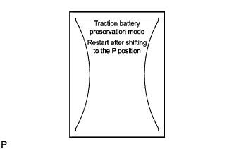
Check whether the HV battery warning message is shown in the multi-information display.
-
Confirm if the engine starts. If the engine starts, leave it idling with park (P) selected until the engine stops (self charge has completed).
If the engine cannot start, follow the procedure and charge the HV battery.
Tech Tips
-
Before performing external charging, always use the GTS to perform troubleshooting.
-
Charging time using the THS charger is 10 minutes per charge cycle. The charging time when using a THS charger is a short charging time (when the battery temperature is 25°C (77°F), 10 minutes may be sufficient; if the battery temperature is 0°C (32°F), then three 10 minute charge cycles may be required) for putting the engine in a condition where it can be started (the system can enter the READY-on state). (The THS charger will automatically stop 10 minutes after charging starts.)
-
-
-
-
PREPARATION FOR HV BATTERY CHARGING (for LHD)
CAUTION:
-
When performing work on high voltage systems, be sure to wear insulated gloves and use insulated tools.
-
Do not start the hybrid system with the service plug grip removed because it may cause a malfunction.
-
Keep the removed service plug grip in your pocket to prevent other technicians from accidentally reconnecting it while you are servicing the vehicle.
-
After removing the service plug grip, wait 10 minutes before touching any of the high voltage connectors or terminals.
Tech Tips
-
Removing the service plug grip interrupts the high voltage circuit.
-
High voltage wiring connectors are orange.
-
Remove the luggage compartment floor mat.
-
Remove the luggage compartment trim cover LH.
-
Disconnect the cable from the auxiliary battery negative (-) terminal.
-
Remove the service plug grip Click here.
-
Remove the inverter cover Click here.
-
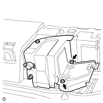
Remove the connector cover assembly Click here.
-
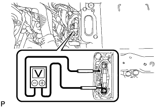
Check the terminal voltage.
CAUTION:
Wear insulated gloves.
Note
Do not allow any foreign objects or water to enter the inverter with converter.
-
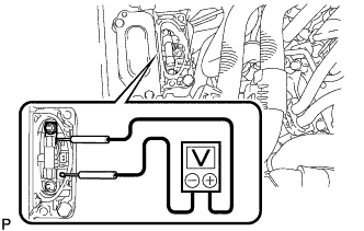
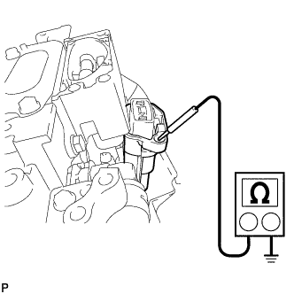
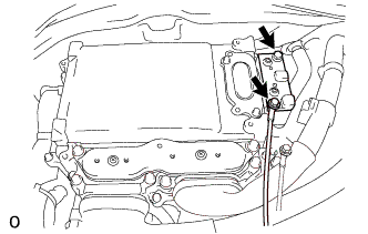
Using a voltmeter, measure the voltage between the terminals of the 2 phase connectors.
Standard voltage 0 V Tech Tips
Use a measuring range of DC 750 V or more on the voltmeter.
-
-
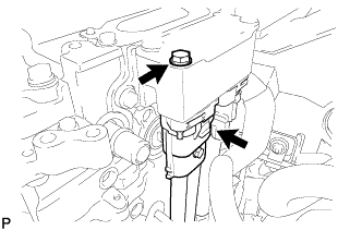
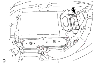
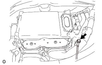
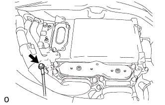
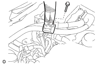
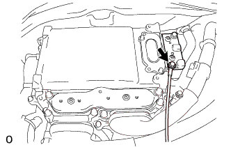
Remove the bolt and disconnect the No. 4 floor wire.
Note
-
Do not damage the terminals, connector housings or inverter with converter assembly when disconnecting them.
-
Do not touch the connector waterproofing rubber or terminals.
-
Insulate the removed terminals with insulating tape.
-
Do not allow any foreign objects or water to enter the inverter with converter assembly.
-
-
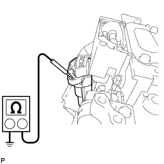
Measure the resistance according to the value(s) in the table below.
Tech Tips
If the shield line of the No. 4 floor wire is not securely connected to body ground, the THS charger will not operate. The "FAULT" and "CABLE CONNECTION" warning lights will illuminate on the THS charger.
Standard Resistance Tester Connection Condition Specified Condition No. 4 floor wire connector housing - Body ground Always Below 1 Ω -
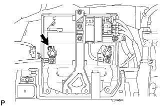
If the result is not as specified, inspect the connection shown in the illustration for proper installation Click here.
-
Temporarily install the connector cover assembly with the bolt to prevent any foreign objects or water from entering the inverter with converter.
-
Connect the THS charger in the order shown in the illustration.
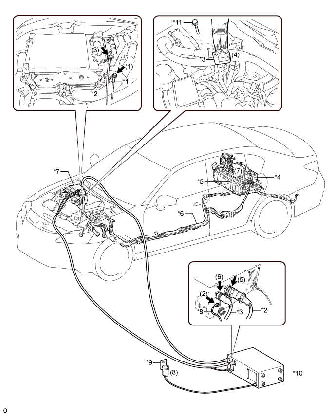
Text in Illustration *1 EV Bonding Cable (Green Cable) *2 Low Voltage Cable *3 High Voltage Cable *4 HV Battery *5 Service Plug Grip *6 No. 4 Floor Wire *7 Inverter with Converter Assembly *8 EV Bonding Cable *9 Grounded AC 100 to 240 V Receptacle *10 THS Charger *11 Bolt (91553-80665) - - - SST
- 09880-10021 ( 09881-10041 )
- 09881-10081
- 09881-10050
- 09882-10040
- 09882-10070
Note
-
Make sure to connect the EV bonding cable first to prevent electrical shock.
-
Connect all THS charger cables in the order shown in the illustration to prevent electrical shock.
-
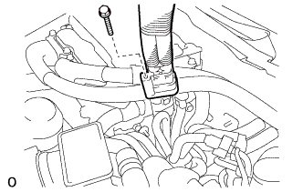
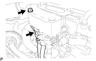
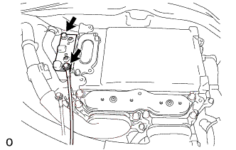
Connect the EV bonding cable to the location where the inverter motor cable bracket assembly was removed with the bolt.
- Torque:
- 8.0 N*m { 82 kgf*cm, 71 in.*lbf }
-
Connect the EV bonding cable to the THS charger.
-
Connect the low voltage cable to the positions shown in the illustration, and then tighten the 2 bolts.
- Torque:
- 8.0 N*m { 82 kgf*cm, 71 in.*lbf }
-
Connect the No. 4 floor wire to the high voltage cable with the bolt (91553-80665).
- Torque:
- 8.0 N*m { 82 kgf*cm, 71 in.*lbf }
Note
-
The installation bolt that comes with the vehicle is too short to securely connect the No. 4 floor wire to the high voltage cable of the charger.
-
Do not use the bolt (91553-80665) used for connecting the high voltage cable when reconnecting the No. 4 floor wire to the vehicle.
Tech Tips
When connecting the high voltage cable, use a bolt with a nominal diameter of 6 mm, a shaft length of 69 mm and a pitch of 1.0 mm.
-
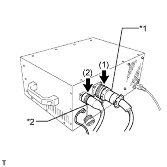
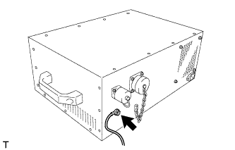
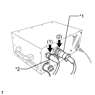
Text in Illustration *1 Low Voltage Cable *2 High Voltage Cable Connect the low voltage cable and high voltage cable to the THS charger in the order shown in the illustration.
-
Install the service plug grip Click here.
-
Connect the cable to the auxiliary battery negative (-) terminal.
- Torque:
- 5.5 N*m { 56 kgf*cm, 49 in.*lbf }
-
Connect the power input plug of the charger to a grounded AC 100 to 240 V receptacle.
Note
Always use an AC 100 to 240 V receptacle with a properly functioning ground. The ground is designed to reduce the chance of electric shock if a malfunction occurs. Do not use the charger if any of the pins on its plug have been damaged or removed.
-
-
PREPARATION FOR HV BATTERY CHARGING (for RHD)
CAUTION:
-
When performing work on high voltage systems, be sure to wear insulated gloves and use insulated tools.
-
Do not start the hybrid system with the service plug grip removed because it may cause a malfunction.
-
Keep the removed service plug grip in your pocket to prevent other technicians from accidentally reconnecting it while you are servicing the vehicle.
-
After removing the service plug grip, wait 10 minutes before touching any of the high voltage connectors or terminals.
Tech Tips
-
Removing the service plug grip interrupts the high voltage circuit.
-
High voltage wiring connectors are orange.
-
Remove the luggage compartment floor mat.
-
Remove the luggage compartment trim cover LH.
-
Disconnect the cable from the auxiliary battery negative (-) terminal.
-
Remove the service plug grip Click here.
-
Remove the inverter cover Click here.
-
Remove the connector cover assembly Click here.
-
Check the terminal voltage.
CAUTION:
Wear insulated gloves.
Note
Do not allow any foreign objects or water to enter the inverter with converter.
-
Using a voltmeter, measure the voltage between the terminals of the 2 phase connectors.
Standard voltage 0 V Tech Tips
Use a measuring range of DC 750 V or more on the voltmeter.
-
-
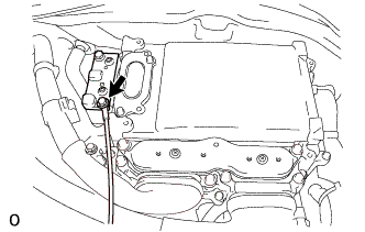
Remove the bolt and disconnect the No. 4 floor wire.
Note
-
Do not damage the terminals, connector housings or inverter with converter assembly when disconnecting them.
-
Do not touch the connector waterproofing rubber or terminals.
-
Insulate the removed terminals with insulating tape.
-
Do not allow any foreign objects or water to enter the inverter with converter assembly.
-
-
Measure the resistance according to the value(s) in the table below.
Tech Tips
If the shield line of the No. 4 floor wire is not securely connected to body ground, the THS charger will not operate. The "FAULT" and "CABLE CONNECTION" warning lights will illuminate on the THS charger.
Standard Resistance Tester Connection Condition Specified Condition No. 4 floor wire connector housing - Body ground Always Below 1 Ω -
If the result is not as specified, inspect the connection shown in the illustration for proper installation Click here.
-
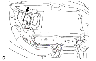
Temporarily install the connector cover assembly with the bolt to prevent any foreign objects or water from entering the inverter with converter.
-
Connect the THS charger in the order shown in the illustration.
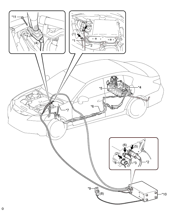
Text in Illustration *1 EV Bonding Cable (Green Cable) *2 Low Voltage Cable *3 High Voltage Cable *4 HV Battery *5 Service Plug Grip *6 No. 4 Floor Wire *7 Inverter with Converter Assembly *8 EV Bonding Cable *9 Grounded AC 100 to 240 V Receptacle *10 THS Charger *11 Bolt (91553-80665) - - - SST
- 09880-10021 ( 09881-10041 )
- 09881-10081
- 09881-10050
- 09882-10040
- 09882-10070
Note
-
Make sure to connect the EV bonding cable first to prevent electrical shock.
-
Connect all THS charger cables in the order shown in the illustration to prevent electrical shock.
-
Connect the EV bonding cable to the location where the inverter motor cable bracket assembly was removed with the bolt.
- Torque:
- 8.0 N*m { 82 kgf*cm, 71 in.*lbf }
-
Connect the EV bonding cable to the THS charger.
-
Connect the low voltage cable to the positions shown in the illustration, and then tighten the 2 bolts.
- Torque:
- 8.0 N*m { 82 kgf*cm, 71 in.*lbf }
-
Connect the No. 4 floor wire to the high voltage cable with the bolt (91553-80665).
- Torque:
- 8.0 N*m { 82 kgf*cm, 71 in.*lbf }
Note
-
The installation bolt that comes with the vehicle is too short to securely connect the No. 4 floor wire to the high voltage cable of the charger.
-
Do not use the bolt (91553-80665) used for connecting the high voltage cable when reconnecting the No. 4 floor wire to the vehicle.
Tech Tips
When connecting the high voltage cable, use a bolt with a nominal diameter of 6 mm, a shaft length of 69 mm and a pitch of 1.0 mm.
-
Text in Illustration *1 Low Voltage Cable *2 High Voltage Cable Connect the low voltage cable and high voltage cable to the THS charger in the order shown in the illustration.
-
Install the service plug grip Click here.
-
Connect the cable to the auxiliary battery negative (-) terminal.
- Torque:
- 5.5 N*m { 56 kgf*cm, 49 in.*lbf }
-
Connect the power input plug of the charger to a grounded AC 100 to 240 V receptacle.
Note
Always use an AC 100 to 240 V receptacle with a properly functioning ground. The ground is designed to reduce the chance of electric shock if a malfunction occurs. Do not use the charger if any of the pins on its plug have been damaged or removed.
-
-
HV BATTERY CHARGING (for LHD)
-
Turn the power switch on (IG).
-
Connect the GTS to the DLC3.
-
Enter the following menus: Powertrain / Hybrid Control / Active Test / Battery Charge.
Tech Tips
-
During the "Battery Charge" Active Test, check "System Main Relay Status - SMRB" and "System Main Relay Status - SMRG" in the Data List.
-
If the Data List values are not as specified in the table below, turn the GTS and the power switch off and then perform the Charge Battery procedure again.
"SMRB" and "SMRG" in Data List during "Battery Charge" Active Test Step Active Test
Battery Charge
THS Charger START
Switch
Data List
System Main Relay Status - SMRB
Data List
System Main Relay Status - SMRG
1 OFF OFF OFF OFF 2 OFF → ON OFF OFF → ON OFF → ON 3 ON OFF → ON ON ON -
-
Make sure that the EMERGENCY STOP switch is in the reset condition (the switch is turned clockwise and released).
-
Make sure that the BREAKER is in the ON position.
-
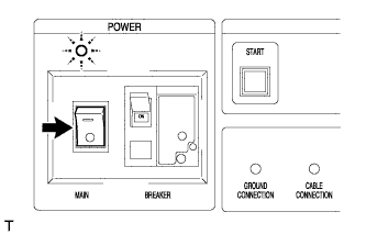
Turn the THS charger MAIN switch on.
Tech Tips
The MAIN indicator will illuminate in green.
-
Press the START switch.
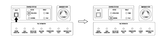
Tech Tips
-
When the START switch is turned on, the INITIAL CHECK indicator illuminates and an initial check starts. When the initial check completes successfully, the INITIAL CHECK indicator turns off, the CHARGING indicator illuminates and charging will start at the same time.
-
While the INITIAL CHECK indicator is illuminated, the insulation, 400 V output, emergency stop switch, connector connections and ground connection are inspected.
-
-
Repeat the charge cycle 3 times. When the last cycle has finished, turn the THS charger MAIN switch off.
Tech Tips
-
Charging time using the THS charger is 10 minutes per charge cycle. The charging time when using a THS charger is a short charging time (when the battery temperature is 25°C (77°F), 10 minutes may be sufficient; if the battery temperature is 0°C (32°F), then three 10 minute charge cycles may be required) for putting the engine in a condition where it can be started (the system can enter the READY-on state). (The THS charger will automatically stop 10 minutes after charging starts.)
-
There is very little chance of overcharging the HV battery during the second or third charging cycle. The SOC will not likely increase beyond the upper limit because it was low enough to prevent the engine from starting. Even if the SOC was to increase enough to exceed the limit, the hybrid vehicle control ECU will stop the Active Test to prevent overcharging.
-
Cranking the engine once causes the SOC to drop approximately 1%.
-
Charging the HV battery once (10 minutes) using the THS charger restores the SOC approximately 2%.
-
-
Turn the power switch off.
-
Remove the THS charger and install the No. 4 floor wire.
Note
Make sure to disconnect the EV bonding cable last.
-
Disconnect the power inlet plug of the charger from the receptacle.
-
Disconnect the cable from the auxiliary battery negative (-) terminal.
-
Remove the service plug grip Click here.
-
Text in Illustration *1 Low Voltage Cable *2 High Voltage Cable Disconnect the high voltage cable and low voltage cable from the THS charger in the order shown in the illustration.
-
Remove the bolt (91553-80665) and disconnect the high voltage cable from the No. 4 floor wire.
Note
Do not use the bolt (91553-80665) used for connecting the high voltage cable when reconnecting the No. 4 floor wire to the vehicle.
-
Remove the bolt and disconnect the low voltage cable.
-
Disconnect the EV bonding cable from the THS charger.
-
Remove the bolt and disconnect the EV bonding cable.
-
Remove the bolt and connector cover assembly.
-
Connect the No. 4 floor wire with the bolt.
- Torque:
- 8.0 N*m { 82 kgf*cm, 71 in.*lbf }
Note
Do not use the bolt (91553-80665) used for connecting the high voltage cable of the charger.
-
Install the connector cover assembly Click here.
-
Install the inverter cover Click here.
-
Install the service plug grip Click here.
-
Connect the cable to the auxiliary battery negative (-) terminal.
- Torque:
- 5.5 N*m { 56 kgf*cm, 49 in.*lbf }
-
Install the luggage compartment trim cover LH.
-
Install the luggage compartment floor mat.
-
-
Check if the engine starts.
Tech Tips
If the engine does not start, perform the HV battery charging operation again.
-
-
HV BATTERY CHARGING (for RHD)
-
Turn the power switch on (IG).
-
Connect the GTS to the DLC3.
-
Enter the following menus: Powertrain / Hybrid Control / Active Test / Battery Charge.
Tech Tips
-
During the "Battery Charge" Active Test, check "System Main Relay Status - SMRB" and "System Main Relay Status - SMRG" in the Data List.
-
If the Data List values are not as specified in the table below, turn the GTS and the power switch off and then perform the Charge Battery procedure again.
"SMRB" and "SMRG" in Data List during "Battery Charge" Active Test Step Active Test
Battery Charge
THS Charger START
Switch
Data List
System Main Relay Status - SMRB
Data List
System Main Relay Status - SMRG
1 OFF OFF OFF OFF 2 OFF → ON OFF OFF → ON OFF → ON 3 ON OFF → ON ON ON -
-
Make sure that the EMERGENCY STOP switch is in the reset condition (the switch is turned clockwise and released).
-
Make sure that the BREAKER is in the ON position.
-
Turn the THS charger MAIN switch on.
Tech Tips
The MAIN indicator will illuminate in green.
-
Press the START switch.
Tech Tips
-
When the START switch is turned on, the INITIAL CHECK indicator illuminates and an initial check starts. When the initial check completes successfully, the INITIAL CHECK indicator turns off, the CHARGING indicator illuminates and charging will start at the same time.
-
While the INITIAL CHECK indicator is illuminated, the insulation, 400 V output, emergency stop switch, connector connections and ground connection are inspected.
-
-
Repeat the charge cycle 3 times. When the last cycle has finished, turn the THS charger MAIN switch off.
Tech Tips
-
Charging time using the THS charger is 10 minutes per charge cycle. The charging time when using a THS charger is a short charging time (when the battery temperature is 25°C (77°F), 10 minutes may be sufficient; if the battery temperature is 0°C (32°F), then three 10 minute charge cycles may be required) for putting the engine in a condition where it can be started (the system can enter the READY-on state). (The THS charger will automatically stop 10 minutes after charging starts.)
-
There is very little chance of overcharging the HV battery during the second or third charging cycle. The SOC will not likely increase beyond the upper limit because it was low enough to prevent the engine from starting. Even if the SOC was to increase enough to exceed the limit, the hybrid vehicle control ECU will stop the Active Test to prevent overcharging.
-
Cranking the engine once causes the SOC to drop approximately 1%.
-
Charging the HV battery once (10 minutes) using the THS charger restores the SOC approximately 2%.
-
-
Turn the power switch off.
-
Remove the THS charger and install the No. 4 floor wire.
Note
Make sure to disconnect the EV bonding cable last.
-
Disconnect the power inlet plug of the charger from the receptacle.
-
Disconnect the cable from the auxiliary battery negative (-) terminal.
-
Remove the service plug grip Click here.
-
Text in Illustration *1 Low Voltage Cable *2 High Voltage Cable Disconnect the high voltage cable and low voltage cable from the THS charger in the order shown in the illustration.
-
Remove the bolt (91553-80665) and disconnect the high voltage cable from the No. 4 floor wire.
Note
Do not use the bolt (91553-80665) used for connecting the high voltage cable when reconnecting the No. 4 floor wire to the vehicle.
-
Remove the bolt and disconnect the low voltage cable.
-
Disconnect the EV bonding cable from the THS charger.
-
Remove the bolt and disconnect the EV bonding cable.
-
Remove the bolt and connector cover assembly.
-
Connect the No. 4 floor wire with the bolt.
- Torque:
- 8.0 N*m { 82 kgf*cm, 71 in.*lbf }
Note
Do not use the bolt (91553-80665) used for connecting the high voltage cable of the charger.
-
Install the connector cover assembly Click here.
-
Install the inverter cover Click here.
-
Install the service plug grip Click here.
-
Connect the cable to the auxiliary battery negative (-) terminal.
- Torque:
- 5.5 N*m { 56 kgf*cm, 49 in.*lbf }
-
Install the luggage compartment trim cover LH.
-
Install the luggage compartment floor mat.
-
-
Check if the engine starts.
Tech Tips
If the engine does not start, perform the HV battery charging operation again.
-
-
CHECK HV BATTERY AFTER HV BATTERY CHARGE
-
Check for DTCs Click here.
-
Perform the self-charging operation.
-
Start the engine and leave park (P) selected until the engine stops idling.
Tech Tips
When the engine stops idling, this indicates that self-charging is complete. Perform any initialization required after the auxiliary battery negative (-) terminal is disconnected and reconnected Click here.
-
-