АККУМУЛЯТОРНАЯ БАТАРЕЯ ГИБРИДНОЙ СИСТЕМЫ, Diagnostic DTC:U029A-123
| DTC Code | DTC Name |
|---|---|
| U029A-123 | Lost Communication with Hybrid Battery Pack Sensor Module |
DESCRIPTION
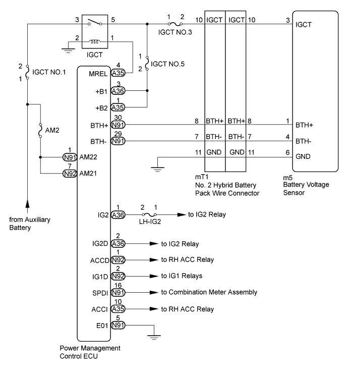
The battery voltage sensor detects the HV battery conditions (voltage, current, and temperature) and the battery cooling fan frequency, and sends the detected signals to the power management control ECU via serial communication. (The power management control ECU does not send signals to the battery voltage sensor.)
| DTC No. | DTC Detection Condition | Trouble Area |
|---|---|---|
| U029A-123 | Serial communication error between the power management control ECU and battery voltage sensor: The power management control ECU cannot receive signals from the battery voltage sensor correctly. (1 trip detection logic) |
|
WIRING DIAGRAM
INSPECTION PROCEDURE
CAUTION:
-
Before inspecting the high-voltage system, take safety precautions to prevent electrical shocks, such as wearing insulated gloves and removing the service plug grip. After removing the service plug grip, put it in your pocket to prevent other technicians from accidentally reconnecting it while you are working on the high-voltage system.
-
After removing the service plug grip, wait for at least 10 minutes before touching any of the high-voltage connectors or terminals. After waiting for 10 minutes, check the voltage at the terminals in the inspection point in the inverter with converter assembly. The voltage should be 0 V before beginning work Click here.
Tech Tips
At least 10 minutes is required to discharge the high-voltage capacitor inside the inverter with converter assembly.
Note
After turning the power switch off, waiting time may be required before disconnecting the cable from the negative (-) auxiliary battery terminal. Therefore, make sure to read the disconnecting the cable from the negative (-) auxiliary battery terminal notices before proceeding with work Click here.
Tech Tips
After the repair, clear the DTCs and perform the following procedure to check that DTCs are not output.
-
Turn the power switch on (IG) and wait for 2 minutes or more.
PROCEDURE
-
CHECK DTC OUTPUT (HYBRID CONTROL)
-
Connect the GTS to the DLC3.
-
Turn the power switch on (IG).
-
Enter the following menus: Powertrain / Hybrid Control / Trouble Codes.
-
Read output DTCs.
Result Result Proceed to Only U029A-123 is output. A DTCs except U029A-123 are also output. B -
Turn the power switch off.
B 
GO TO DTC CHART (HYBRID BATTERY SYSTEM) Click here
A 
-
-
CHECK HARNESS AND CONNECTOR (IGCT VOLTAGE)
CAUTION:
Be sure to wear insulated gloves.
-
Check that the service plug grip is not installed.
Note
After removing the service plug grip, do not turn the power switch on (READY), unless instructed by the repair manual because this may cause a malfunction.
-
Remove the front luggage compartment trim cover Click here.
-
Connect the cable to the negative (-) auxiliary battery terminal.
-
Turn the power switch on (IG).
-
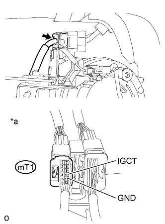
Text in Illustration *a Component with harness connected
(No. 2 Hybrid Battery Pack Wire Connector)
Measure the voltage according to the value(s) in the table below.
Standard Voltage Tester Connection Switch Condition Specified Condition mT1-10 (IGCT) - mT1-11 (GND) Power switch on (IG) 11 to 14 V Note
Turning the power switch on (IG) with the service grip removed causes other DTCs to be stored. Clear the DTCs after performing this inspection.
-
Turn the power switch off.
-
Disconnect the cable from the negative (-) auxiliary battery terminal.
-
Install the front luggage compartment trim cover.
NG
REPAIR OR REPLACE HARNESS OR CONNECTOR (BATTERY VOLTAGE SENSOR POWER SOURCE CIRCUIT)
OK
-
-
CHECK HARNESS AND CONNECTOR (IGCT VOLTAGE)
CAUTION:
Be sure to wear insulated gloves.
-
Check that the service plug grip is not installed.
Note
After removing the service plug grip, do not turn the power switch on (READY), unless instructed by the repair manual because this may cause a malfunction.
-
Remove the upper hybrid battery cover sub-assembly Click here.
-
Connect the cable to the negative (-) auxiliary battery terminal.
-
Turn the power switch on (IG).
-
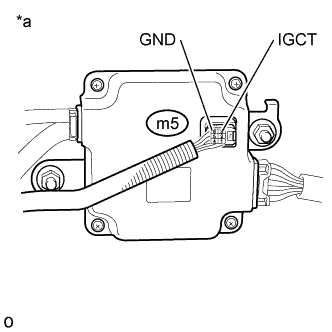
Text in Illustration *a Component with harness connected
(Battery Voltage Sensor)
Measure the voltage according to the value(s) in the table below.
Standard Voltage: Tester Connection Switch Condition Specified Condition m5-3 (IGCT) - m5-6 (GND) Power switch on (IG) 11 to 14 V Note
Turning the power switch on (IG) with the service grip removed causes other DTCs to be stored. Clear the DTCs after performing this inspection.
-
Turn the power switch off.
-
Disconnect the cable from the negative (-) auxiliary battery terminal.
-
Install the upper hybrid battery cover sub-assembly.
NG
REPAIR OR REPLACE HARNESS OR CONNECTOR (BATTERY VOLTAGE SENSOR POWER SOURCE CIRCUIT)
OK
-
-
CHECK HARNESS AND CONNECTOR (POWER MANAGEMENT CONTROL ECU - NO. 2 HYBRID BATTERY PACK WIRE CONNECTOR)
CAUTION:
Be sure to wear insulated gloves.
-
Check that the service plug grip is not installed.
Note
After removing the service plug grip, do not turn the power switch on (READY), unless instructed by the repair manual because this may cause a malfunction.
-
Disconnect N91 connector from the power management control ECU.
Note
-
Before disconnecting the connector, push in on the connector body to check that the connector is not loose or disconnected.
-
Push in on each connector between the power management control ECU and the No. 2 hybrid battery pack wire connector to check that each connector is not loose or disconnected.
-
-
Remove the front luggage compartment trim cover Click here.
-
Disconnect mT1 connector from the No. 2 hybrid battery pack wire connector.
-
Measure the resistance according to the value(s) in the table below.
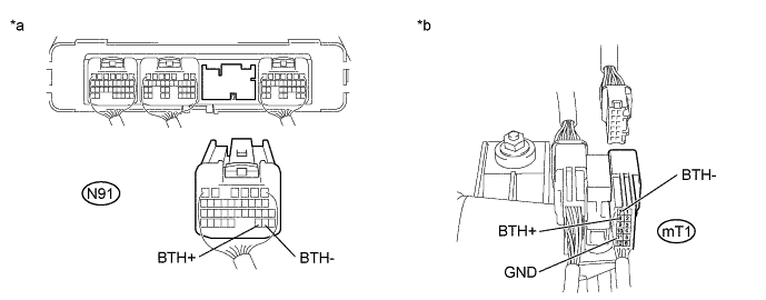
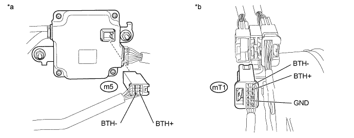
Text in Illustration *a Rear view of wire harness connector
(to Power Management Control ECU)
*b Rear view of wire harness connector
(to No. 2 Hybrid Battery Pack Wire Connector)
Standard Resistance Tester Connection Switch Condition Specified Condition N91-30 (BTH+) - mT1-8 (BTH+) Power switch off Below 1 Ω N91-29 (BTH-) - mT1-7 (BTH-) Power switch off Below 1 Ω mT1-8 (BTH+) - mT1-11 (GND) and Body ground Power switch off 10 kΩ or higher mT1-7 (BTH-) - mT1-11 (GND) and Body ground Power switch off 10 kΩ or higher -
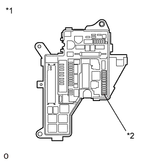
Text in Illustration *1 No. 1 Engine Room Relay Block and Junction Block Assembly *2 IGCT NO.5 fuse Remove the IGCT NO.5 fuse from the No. 1 engine room relay block and junction block assembly.
-
for LHD:
-
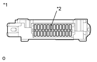
Text in Illustration *1 Cowl Side Junction Block LH *2 LH-IG2 fuse Remove the LH-IG2 fuse from the cowl side junction block LH.
-
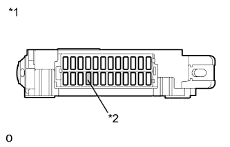
Text in Illustration *1 Cowl Side Junction Block RH *2 AM2 fuse Remove the AM2 fuse from the cowl side junction block RH.
-
-
for RHD:
-
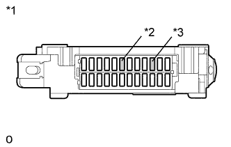
Text in Illustration *1 Cowl Side Junction Block LH *2 LH-IG2 fuse *3 AM2 fuse Remove the LH-IG2 fuse and AM2 fuse from the cowl side junction block LH.
-
-
Disconnect all connectors from the power management control ECU.
-
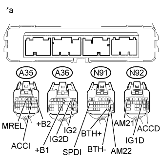
Text in Illustration *a Rear view of wire harness connector
(to Power Management Control ECU)
Measure the resistance according to the value(s) in the table below.
Standard Resistance Tester Connection Switch Condition Specified Condition N91-30 (BTH+) - N92-7 (AM21) Power switch off 10 kΩ or higher N91-30 (BTH+) - N91-1 (AM22) Power switch off 10 kΩ or higher N91-30 (BTH+) - A35-1 (+B2) Power switch off 10 kΩ or higher N91-30 (BTH+) - A36-3 (+B1) Power switch off 10 kΩ or higher N91-30 (BTH+) - A35-4 (MREL) Power switch off 10 kΩ or higher N91-30 (BTH+) - A35-10 (ACCI) Power switch off 10 kΩ or higher N91-30 (BTH+) - A36-1 (IG2) Power switch off 10 kΩ or higher N91-30 (BTH+) - N92-1 (ACCD) Power switch off 10 kΩ or higher N91-30 (BTH+) - N92-2 (IG1D) Power switch off 10 kΩ or higher N91-30 (BTH+) - A36-2 (IG2D) Power switch off 10 kΩ or higher N91-30 (BTH+) - N91-16 (SPDI) Power switch off 10 kΩ or higher N91-29 (BTH-) - N92-7 (AM21) Power switch off 10 kΩ or higher N91-29 (BTH-) - N91-1 (AM22) Power switch off 10 kΩ or higher N91-29 (BTH-) - A35-1 (+B2) Power switch off 10 kΩ or higher N91-29 (BTH-) - A36-3 (+B1) Power switch off 10 kΩ or higher N91-29 (BTH-) - A35-4 (MREL) Power switch off 10 kΩ or higher N91-29 (BTH-) - A35-10 (ACCI) Power switch off 10 kΩ or higher N91-29 (BTH-) - A36-1 (IG2) Power switch off 10 kΩ or higher N91-29 (BTH-) - N92-1 (ACCD) Power switch off 10 kΩ or higher N91-29 (BTH-) - N92-2 (IG1D) Power switch off 10 kΩ or higher N91-29 (BTH-) - A36-2 (IG2D) Power switch off 10 kΩ or higher N91-29 (BTH-) - N91-16 (SPDI) Power switch off 10 kΩ or higher Note
When taking a measurement with a tester, do not apply excessive force to the tester probe to avoid damaging the holder.
-
for LHD:
-
Install the AM2 fuse to the cowl side junction block RH.
-
Install the LH-IG2 fuse to the cowl side junction block LH.
-
-
for RHD:
-
Install the LH-IG2 fuse and AM2 fuse to the cowl side junction block LH.
-
-
Install the IGCT NO.5 fuse to the No. 1 engine room relay block and junction block assembly.
-
Connect the power management control ECU connectors.
-
Connect the No. 2 hybrid battery pack wire connector.
-
Install the front luggage compartment trim cover.
NG
REPAIR OR REPLACE HARNESS OR CONNECTOR (POWER MANAGEMENT)
OK
-
-
CHECK HARNESS AND CONNECTOR (BATTERY VOLTAGE SENSOR - NO. 2 HYBRID BATTERY PACK WIRE CONNECTOR)
CAUTION:
Be sure to wear insulated gloves.
-
Check that the service plug grip is not installed.
Note
After removing the service plug grip, do not turn the power switch on (READY), unless instructed by the repair manual because this may cause a malfunction.
-
Remove the upper hybrid battery cover sub-assembly Click here.
-
Disconnect the m5 battery voltage sensor connector.
-
Disconnect the mT1 No. 2 hybrid battery pack wire connector.
-
Measure the resistance according to the value(s) in the table below.
Text in Illustration *a Rear view of wire harness connector
(to Battery Voltage Sensor)
*b Rear view of wire harness connector
(to No. 2 Hybrid Battery Pack Wire Connector)
Standard Resistance Tester Connection Switch Condition Specified Condition m5-1 (BTH+) - mT1-8 (BTH+) Power switch off Below 1 Ω m5-4 (BTH-) - mT1-7 (BTH-) Power switch off Below 1 Ω mT1-8 (BTH+) - mT1-11 (GND) and Body ground Power switch off 10 kΩ or higher mT1-7 (BTH-) - mT1-11 (GND) and Body ground Power switch off 10 kΩ or higher Note
When taking a measurement with a tester, do not apply excessive force to the tester probe to avoid damaging the holder.
-
Connect the mT1 No. 2 hybrid battery pack wire connector.
-
Connect the m5 battery voltage sensor.
-
Install the upper hybrid battery cover sub-assembly.
NG
REPAIR OR REPLACE HARNESS OR CONNECTOR (POWER MANAGEMENT)
OK
-
-
CHECK POWER MANAGEMENT CONTROL ECU
CAUTION:
Be sure to wear insulated gloves.
-
Check that the service plug grip is not installed.
Note
After removing the service plug grip, do not turn the power switch on (READY), unless instructed by the repair manual because this may cause a malfunction.
-
Remove the upper hybrid battery cover sub-assembly Click here.
-
Disconnect the m5 battery voltage sensor connector.
-
Connect the cable to the negative (-) auxiliary battery terminal.
-
Turn the power switch on (IG).
-
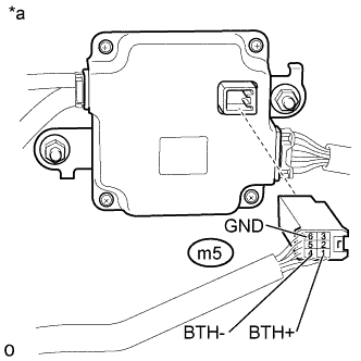
Text in Illustration *a Rear view of wire harness connector
(to Battery Voltage Sensor)
Measure the voltage according to the value(s) in the table below.
Standard Voltage Tester Connection Switch Condition Specified Condition m5-1 (BTH+) - m5-6 (GND) Power switch on (IG) 2.3 to 2.7 V m5-4 (BTH-) - m5-6 (GND) Power switch on (IG) 2.3 to 2.7 V Note
If the power switch is turned on (IG) with the connectors disconnected, other DTCs will be stored. Be sure to clear the DTCs after the inspection.
-
Turn the power switch off.
-
Disconnect the cable from the negative (-) auxiliary battery terminal.
-
Measure the resistance according to the value(s) in the table below.
Standard Resistance Tester Connection Switch Condition Specified Condition m5-1 (BTH+) - m5-4 (BTH-) Power switch off 4.4 to 5.4 kΩ Tech Tips
Resistance becomes 2.0 kΩ or less when there is a short circuit in the power management control ECU.
-
Reconnect the m5 battery voltage sensor connector.
-
Install the upper hybrid battery cover sub-assembly.
NG
REPLACE POWER MANAGEMENT CONTROL ECU Click here
OK 
REPLACE BATTERY VOLTAGE SENSOR Click here
-