БЛОК КОНТРОЛЯ СОСТОЯНИЯ АККУМУЛЯТОРНОЙ БАТАРЕИ СНЯТИЕ
-
CHECK PART NUMBER OF BATTERY SMART UNIT
If the battery smart unit had been replaced just before the malfunction occurred, check the part number of the battery smart unit.
Note
-
The type of battery smart unit to be used varies depending on the vehicle model.
-
If the wrong type of battery smart unit is installed, the power switch cannot be turned on (READY).
-
After installing the battery smart unit, perform the following to check that the power switch can be turned on (READY).
-
Turn the power switch on (READY).
-
Turn the power switch off and wait for 30 seconds or more.
-
Turn the power switch on (READY) again.
-
-
PRECAUTION
CAUTION:
Be sure to read Precaution thoroughly before servicing Click here.
Note
After turning the power switch off, waiting time may be required before disconnecting the cable from the auxiliary battery negative (-) terminal. Therefore, make sure to read the disconnecting the cable from the auxiliary battery negative (-) terminal notices before proceeding with work Click here.
-
READ OUTPUT DTC
-
Check for DTCs Click here.
Note
Confirm that P0AA6 (Hybrid Battery Voltage System Isolation Fault) is not output before performing removal or installation work on the internal parts of the battery. If the DTC is output, perform troubleshooting procedures first.
-
-
REMOVE LUGGAGE COMPARTMENT FLOOR MAT
-
Снимите напольный коврик багажного отделения.
-
-
REMOVE LUGGAGE COMPARTMENT TRIM COVER LH
-
Снимите левую облицовочную накладку багажного отделения.
-
-
DISCONNECT CABLE FROM AUXILIARY BATTERY TERMINAL
Note
When disconnecting the cable, some systems need to be initialized after the cable is reconnected Click here.
-
Disconnect the cable from the auxiliary battery negative (-) terminal.
Tech Tips
Both cables should be disconnected to prevent the AMD terminal from shorting to ground.
-
Remove the terminal cover.
-
Remove the nut and disconnect the cable from the auxiliary battery positive (+) terminal.
Tech Tips
Both cables should be disconnected to prevent the AMD terminal from shorting to ground.
-
-
REMOVE NO. 1 SEAT ARMREST CAP
-
Освободите 4 захвата и 4 направляющие и снимите колпачок подлокотника сиденья № 1.
-
-
REMOVE LOWER HYBRID VEHICLE BATTERY COVER PANEL
CAUTION:
Perform work using insulated gloves and insulated tools.
-
Remove the 4 nuts and lower hybrid vehicle battery cover panel.
-
-
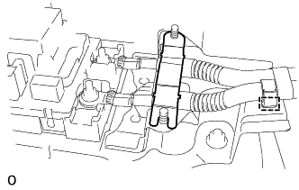
REMOVE SERVICE PLUG GRIP
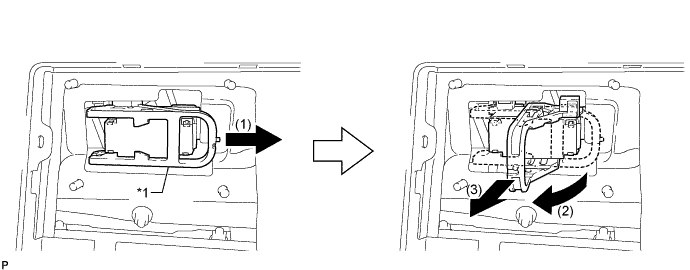
Text in Illustration *1 Lever - -
-
Remove the service plug grip in the order shown in the illustration.
CAUTION:
-
Wear insulated gloves.
-
Remove the service plug grip to interrupt a high voltage circuit at the time of the check.
-
Keep the removed service plug grip in your pocket to prevent other technicians from accidentally reconnecting it while you are servicing the vehicle.
-
After disconnecting the service plug grip, wait at least 10 minutes before touching any of the high-voltage connectors or terminals.
-
Never turn the power switch on (READY) with the service plug grip removed as malfunctions may occur.
Tech Tips
-
Waiting for at least 10 minutes is required to discharge the high-voltage capacitor inside the inverter with converter assembly.
-
High voltage wiring connectors are orange.
-
Slide the lever and release the lock.
-
Raise the lever and pull the service plug grip to remove it.
-
-
-
REMOVE INVERTER COVER
-
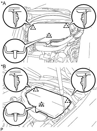
Text in Illustration *A for LHD *B for RHD Raise the front of the inverter cover to detach the clip. Then remove the 2 inverter cover clips from the bracket, and remove the inverter cover.
-
-
REMOVE CONNECTOR COVER ASSEMBLY
CAUTION:
-
Do not touch the high voltage connectors and terminals for 10 minutes after the service plug grip is removed.
-
Wear insulated gloves.
Note
Do not start the hybrid system with the service plug grip removed because it may cause a malfunction.
-
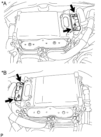
Text in Illustration *A for LHD *B for RHD Using an insulated tool, remove the 2 bolts and connector cover assembly.
Note
-
Make sure to pull the connector cover assembly straight up, as a connector is connected to the bottom of the connector cover assembly.
-
Do not allow any foreign objects or water to enter the inverter with converter assembly.
-
-
-
CHECK TERMINAL VOLTAGE
CAUTION:
Wear insulated gloves.
Note
Do not allow any foreign objects or water to enter the inverter with converter assembly.
-
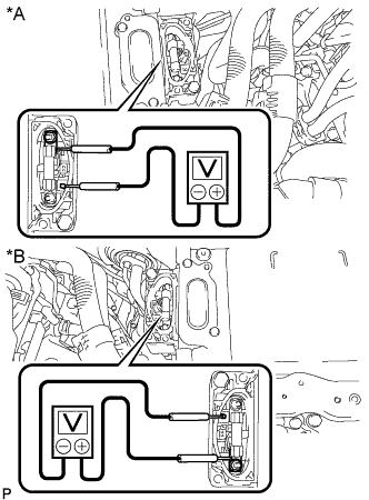
Text in Illustration *A for LHD *B for RHD Using a voltmeter, measure the voltage between the terminals of the 2 phase connectors.
Standard voltage 0 V Tech Tips
Use a measuring range of DC 750 V or more on the voltmeter.
-
-
INSTALL CONNECTOR COVER ASSEMBLY
CAUTION:
Wear insulated gloves.
Note
-
Make sure that the interlock is fully engaged.
-
Do not allow any foreign objects or water to enter the inverter with converter assembly.
-
Using an insulated tool, install the connector cover assembly with the 2 bolts.
- Torque:
- 8.0 N*m { 82 kgf*cm, 71 in.*lbf }
-
-
INSTALL INVERTER COVER
-
Attach the 2 inverter cover claws to the inverter with converter. Then attach the inverter cover with the clip.
-
-
REMOVE REAR SEAT ASSEMBLY
-
REMOVE REAR DOOR SCUFF PLATE LH
-
Поместите руки на внутреннюю часть накладки порога левой задней двери и отсоедините 2 захвата, обозначенных A, 6 захватов, обозначенных B, и 2 захвата, обозначенных C, в порядке, показанном на рисунке.
-
Поднимите накладку порога левой задней двери, чтобы отсоединить 4 фиксатора с наружной стороны, и снимите ее.
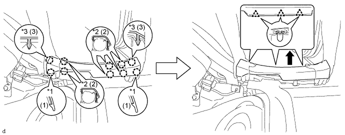
Обозначения на рисунке *1 Захват A *2 Захват B *3 Захват C - -
-
-
REMOVE REAR SEAT SIDE GARNISH LH

-
Отсоедините 4 захвата и направляющую и снимите левую боковой облицовки заднего сиденья.
-
-
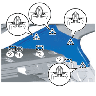
REMOVE INNER ROOF SIDE GARNISH LH
-
С задним солнцезащитным навесом:
-
Освободите 4 фиксатора.
-
Отсоединив 3 направляющие и край шторки заднего окна, снимите внутреннюю левую боковую облицовку крыши.
Обозначения на рисунке *1 Край шторки заднего окна *2 Направляющая
-
-
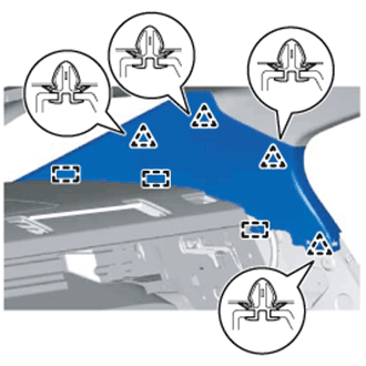
Без заднего солнцезащитного навеса:
-
Отсоединив 4 фиксатора и 3 направляющие, снимите внутреннюю левую боковую облицовку крыши.
-
-
-
REMOVE REAR DOOR SCUFF PLATE RH
Tech Tips
Порядок выполнения работ такой же, как для левой стороны.
-
REMOVE REAR SEAT SIDE GARNISH RH
Tech Tips
Порядок выполнения работ такой же, как для левой стороны.
-
REMOVE INNER ROOF SIDE GARNISH RH
Tech Tips
Порядок выполнения работ такой же, как для левой стороны.
-
REMOVE PACKAGE TRAY TRIM PANEL ASSEMBLY
-
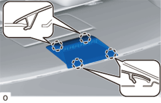
С помощью съемника молдингов отсоедините 4 захвата и снимите крышку отверстия плечевого крепления ремня безопасности заднего сиденья.
Tech Tips
Выполните эту же операцию, чтобы снять крышку отверстия плечевого крепления ремня безопасности заднего сиденья с другой стороны.
-
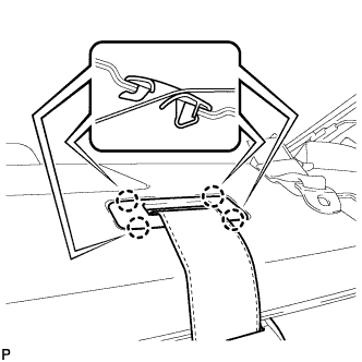
С помощью съемника молдингов освободите 4 захвата и снимите направляющую ремня левого замка ремня безопасности заднего сиденья с центральным ремнем в сборе.
-
Без заднего солнцезащитного навеса:
-
Освободите 4 захвата и снимите колпак центрального стоп-сигнала.
-
Отсоедините разъем.
-
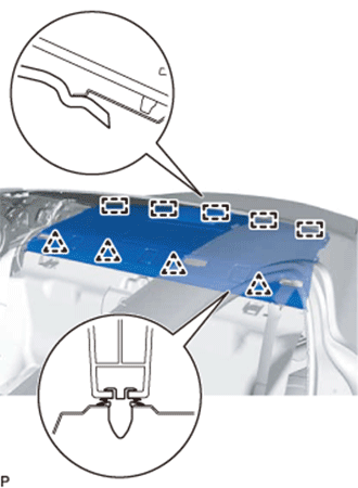
Освободите 4 фиксатора и затем сдвиньте панель облицовки отделения для мелких вещей в направлении передней части автомобиля, чтобы освободить 5 направляющих.
-
Пропустите 3 напольных крепления ремней безопасности заднего сиденья через облицовку отделения для мелких вещей, а затем снимите облицовку отделения для мелких вещей в сборе.
-
-
С задним солнцезащитным навесом:
-
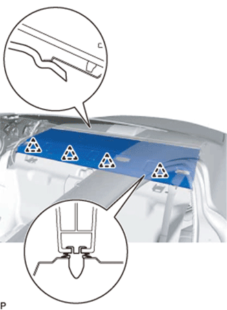
Освободите 4 фиксатора и затем сдвиньте панель облицовки отделения для мелких вещей в направлении передней части автомобиля, чтобы отсоединить ее от шторки окна задней двери в сборе.
-
Пропустите 3 напольных крепления ремней безопасности заднего сиденья через облицовку отделения для мелких вещей, а затем снимите облицовку отделения для мелких вещей в сборе.
-
-
-
REMOVE CENTER STOP LIGHT COVER (w/ Rear Sunshade)
-
Освободите 4 захвата и снимите колпак центрального стоп-сигнала.
-
Отсоедините разъем.
-
-
REMOVE NO. 2 PACKAGE TRAY TRIM PANEL ASSEMBLY (w/ Rear Sunshade)
-
Расцепите 3 фиксатора и 5 направляющих и снимите панель облицовки отделения для мелких вещей № 2 в сборе.
-
-
REMOVE NO. 2 ROOM PARTITION PAD
-
С помощью съемника фиксаторов снимите 2 фиксатора и разделительную подкладку салона № 2.
-
-
REMOVE NO. 1 ROOM PARTITION PAD
-
С помощью съемника фиксаторов снимите 5 фиксаторов и разделительную подкладку салона № 1.
-
-
REMOVE LUGGAGE COMPARTMENT TRIM COVER RH
-
Снимите правую облицовочную накладку багажного отделения.
-
-
REMOVE SIDE TRIM BOX
-
Снимите боковую облицовочную коробку.
-
-
REMOVE LUGGAGE COMPARTMENT SIDE TRAY (w/ Spare Tire)
-
Снимите боковой поддон багажного отделения.
-
-
REMOVE LUGGAGE COMPARTMENT TRIM BOX (w/o Spare Tire)
-
Снимите облицовочную коробку багажного отделения.
-
-
REMOVE SPARE WHEEL COVER TRAY (w/o Spare Tire)
-
Снимите поддон чехла запасного колеса.
-
-
REMOVE ROPE HOOK ASSEMBLY
Tech Tips
Порядок выполнения работ одинаков для всех канатных крюков.
-
Отсоедините 2 захвата и откройте обивку.
-
Выверните болт и снимите канатный крюк в сборе.
-
-
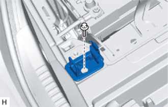
REMOVE REAR LUGGAGE COMPARTMENT TRAY BRACKET LH
-
Снимите фиксатор.
-
Освободите захват и снимите левый задний кронштейн поддона багажного отделения.
-
-
REMOVE REAR LUGGAGE COMPARTMENT TRAY BRACKET RH
Tech Tips
Порядок выполнения работ такой же, как для левой стороны.
-
REMOVE NO. 1 LUGGAGE COMPARTMENT TRIM HOOK
-
Отсоедините 2 захвата и снимите защелку облицовки багажного отделения № 1.
-
-
REMOVE NO. 1 LUGGAGE COMPARTMENT LIGHT ASSEMBLY
-
Обозначения на рисунке *1 Защитная клейкая лента С помощью отвертки с обернутым защитной лентой концом отсоедините 2 захвата и снимите лампу освещения багажного отделения № 1 в сборе.
-
Отсоедините разъем.
-
-
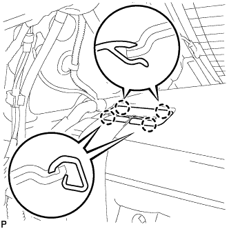
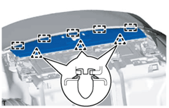
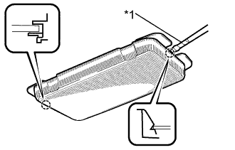
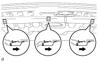
REMOVE REAR LUGGAGE COMPARTMENT TRIM COVER
-
Снимите 3 защелки облицовки багажного отделения № 2, как показано на рисунке.
-
Снимите 5 фиксатора.
-
Открепите 3 направляющих и снимите заднюю облицовочную накладку багажного отделения.
-
-
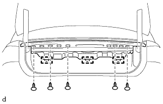
REMOVE REAR FLOOR FINISH PLATE
-
Снимите 3 фиксатора.
-

Освободите 6 фиксаторов и снимите отделочную пластину заднего пола.
-
-
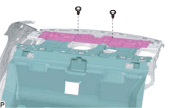
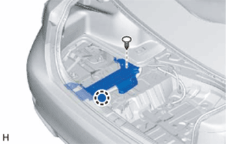
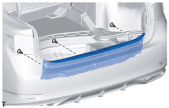
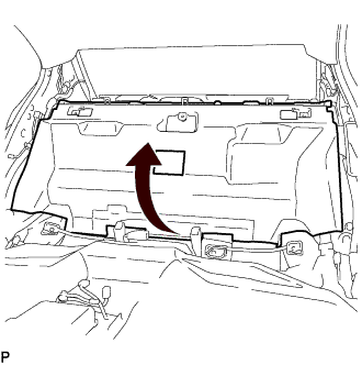
REMOVE FRONT LUGGAGE COMPARTMENT TRIM COVER
-
Снимите 3 фиксатора, 2 гайки и переднюю облицовочную накладку багажного отделения.
-
-
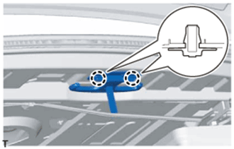
REMOVE ROPE HOOK
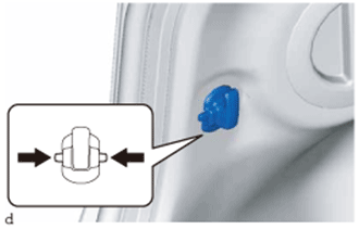
Tech Tips
Порядок выполнения работ одинаков для обоих канатных крюков.
-
Сожмите канатный крюк, как показано на рисунке стрелками, чтобы извлечь его.
-
-
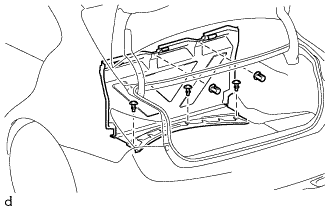
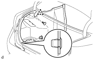
REMOVE INNER LUGGAGE COMPARTMENT TRIM COVER LH
-
С помощью съемника фиксаторов освободите фиксатор.
-
Освободите 2 захвата и снимите фиксатор.
-
Освободите фиксатор и снимите левую внутреннюю облицовочную накладку багажного отделения.
-
-
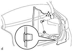
REMOVE INNER LUGGAGE COMPARTMENT TRIM COVER RH
-
С помощью съемника фиксаторов освободите фиксатор.
-
Освободите 2 захвата и снимите фиксатор.
-
Освободите фиксатор и снимите правую внутреннюю облицовочную накладку багажного отделения.
-
-
REMOVE NO. 6 HYBRID BATTERY INTAKE DUCT
Tech Tips
If the message "Cooling performance of the hybrid battery is low Consult a dealer" is displayed on the multi-information display in the combination meter assembly, inspect the No. 6 hybrid battery intake duct after removing it Click here.
-
Roll up the No. 1 room partition pad.
-
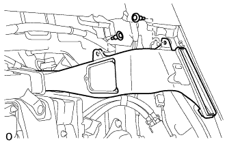
Remove the 2 clips.
-
Disconnect the No. 6 hybrid battery intake duct from the No. 3 hybrid battery intake duct and remove it.
-
-
REMOVE NO. 1 HYBRID BATTERY INTAKE DUCT
Tech Tips
If the message "Cooling performance of the hybrid battery is low Consult a dealer" is displayed on the multi-information display in the combination meter assembly, inspect the No. 1 hybrid battery intake duct after removing it Click here.
-
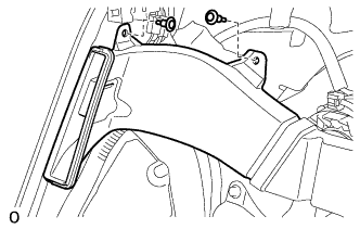
Remove the 2 clips.
-
Disconnect the No. 1 hybrid battery intake duct from the No. 3 hybrid battery intake duct and remove it.
-
-
REMOVE NO. 3 HYBRID BATTERY INTAKE DUCT
-
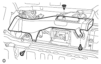
Remove the 3 clips.
-
Disconnect the No. 3 hybrid battery intake duct from the battery cooling blower assembly and remove it.
-
-
REMOVE NO. 4 HYBRID VEHICLE BATTERY SHIELD SUB-ASSEMBLY
CAUTION:
Perform work using insulated gloves and insulated tools.
-
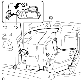
Text in Illustration *1 Battery Cover Lock Striker *2 Button *a Counterclockwise *b Protrusion Using the service plug grip, insert the protrusion part of the service plug grip, turn the button of the battery cover lock striker counterclockwise, and release the lock.
-
Remove the 4 nuts and No. 4 hybrid vehicle battery shield sub-assembly.
-
-
DISCONNECT NO. 4 FLOOR WIRE
CAUTION:
Perform work using insulated gloves and insulated tools.
-
Remove the battery shield contact.
-
Detach the wire harness clamp.
-
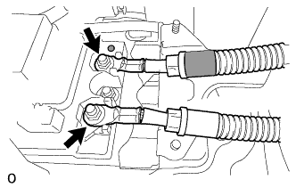
Remove the 2 nuts and disconnect the 2 wires of the No. 4 floor wire.
Note
Insulate the terminals of the disconnected high voltage wire with insulating tape.
-
-
REMOVE NO. 1 HYBRID BATTERY CARRIER BRACKET
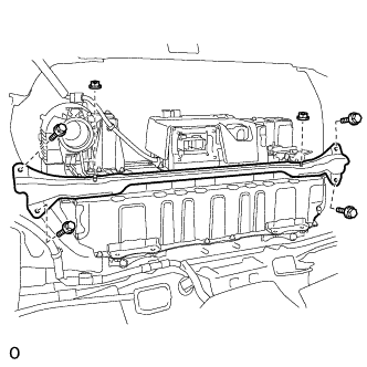
CAUTION:
Be sure to wear insulated gloves.
-
Remove the 2 nuts.
-
Remove the 4 bolts and No. 1 hybrid battery carrier bracket.
-
-
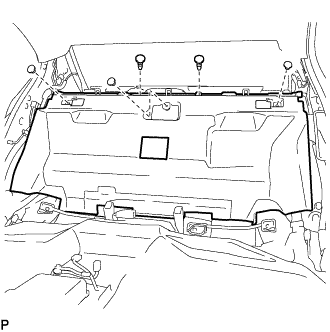
REMOVE UPPER HYBRID BATTERY COVER SUB-ASSEMBLY
CAUTION:
Perform work using insulated gloves and insulated tools.
-
Detach the wire harness clamp.
-
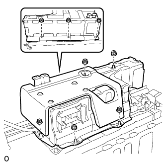
Remove the 8 nuts and upper hybrid battery cover sub-assembly.
-
-
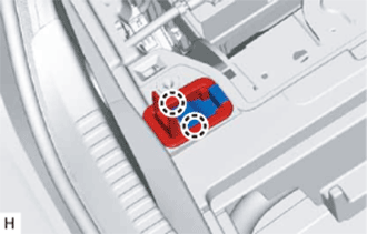
REMOVE HYBRID BATTERY JUNCTION BLOCK ASSEMBLY
CAUTION:
Perform work using insulated gloves and insulated tools.
-
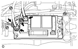
Disconnect the 4 connectors.
Note
Insulate the disconnected high voltage connectors with insulating tape.
Tech Tips
High voltage wiring connectors are orange.
-
Remove the 3 nuts and hybrid battery junction block assembly.
Note
If the hybrid battery junction block assembly has been dropped, replace it with a new one.
-
-
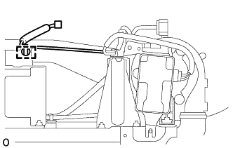
REMOVE BATTERY SMART UNIT
CAUTION:
Perform work using insulated gloves and insulated tools.
-
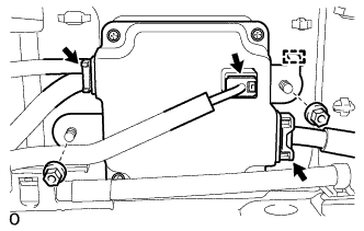
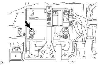
Disconnect the 3 connectors.
Note
Insulate the disconnected high voltage connectors with insulating tape.
Tech Tips
High voltage wiring connectors are orange.
-
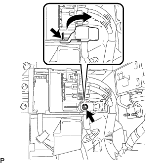
Remove the 2 nuts.
-
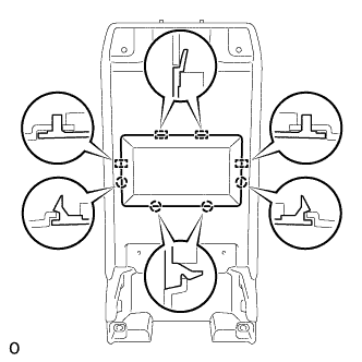
Detach the guide and remove the battery smart unit.
-