ПРЕОБРАЗОВАТЕЛЬ-ИНВЕРТОР УСТАНОВКА
-
INSTALL HIGH VOLTAGE FUSE
CAUTION:
Wear insulated gloves.
Tech Tips
Perform this procedure only when replacement of the high voltage fuse is necessary.
-
Remove the bolt and connector cover assembly.
Note
-
Make sure to pull the connector cover assembly straight up, as a connector is connected to the bottom of the cover.
-
Do not allow any foreign objects or water to enter the inverter with converter assembly.
-
-
Install the high voltage fuse with 2 new nuts.
- Torque:
- 4.0 N*m { 41 kgf*cm, 35 in.*lbf }
Note
Be sure to use a torque wrench to tighten the nuts.
-
Temporarily install the connector cover assembly with the bolt to prevent any foreign objects or water from entering the inverter with converter assembly.
-
-
INSTALL INVERTER BUS-BAR PLATE SUB-ASSEMBLY
-
Temporarily install the inverter bus-bar plate sub-assembly with the nut by tightening the nut 3 or more revolutions.
-
Install the bolt and attach the clamp.
- Torque:
- 8.0 N*m { 82 kgf*cm, 71 in.*lbf }
-
Tighten the nut.
- Torque:
- 18 N*m { 184 kgf*cm, 13 ft.*lbf }
-
Close the cover.
-
-
INSTALL NO. 4 INVERTER BRACKET
-
Install the No. 4 inverter bracket with the 2 bolts.
- Torque:
- 8.0 N*m { 82 kgf*cm, 71 in.*lbf }
-
for RHD:
Install the wire harness bracket with the bolt.
- Torque:
- 10 N*m { 102 kgf*cm, 7 ft.*lbf }
-
-
INSTALL INVERTER WITH CONVERTER ASSEMBLY
CAUTION:
Wear insulated gloves.
-
Temporarily install the No. 6 inverter bracket and inverter with converter assembly with the 6 bolts.
Note
-
Since the inverter with converter assembly is very heavy, 2 people are needed to install the inverter with converter assembly. When installing the inverter with converter assembly, do not damage the parts around it.
-
To prevent damage, do not hold the inverter with converter assembly by the connectors.
-
To prevent damage due to static electricity, do not touch the terminals of the disconnected connectors.
-
-
Remove the bolt and connector cover assembly.
Note
-
Make sure to pull the connector cover assembly straight up, as a connector is connected to the bottom of the connector cover assembly.
-
Do not allow any foreign objects or water to enter the inverter with converter assembly.
-
-
Connect the No. 4 floor wire to the inverter with converter assembly.
Note
-
Do not damage the terminals, connector housings or inverter with converter assembly when connecting them.
-
Do not touch the connector waterproofing rubber or terminals.
-
Do not allow any foreign objects or water to enter the inverter with converter assembly.
-
Make sure that the connectors are fully engaged.
-
Make sure that the connector does not come out when its body is pulled.
-
-
Secure the No. 4 floor wire to the inverter with converter assembly with the bolt.
- Torque:
- 8.0 N*m { 82 kgf*cm, 71 in.*lbf }
-
Connect the air conditioning harness to the inverter with converter assembly.
Note
-
Do not damage the terminals, connector housings or inverter with converter assembly when connecting them.
-
Do not touch the connector waterproofing rubber or terminals.
-
Do not allow any foreign objects or water to enter the inverter with converter assembly.
-
Make sure that the connectors are fully engaged.
-
Make sure that the connector does not come out when its body is pulled.
-
-
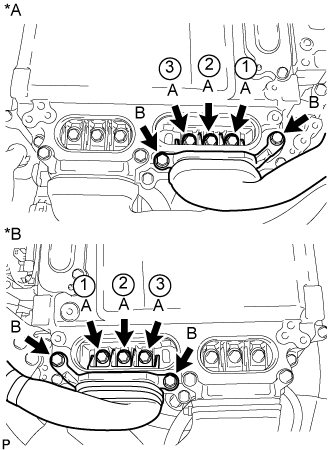
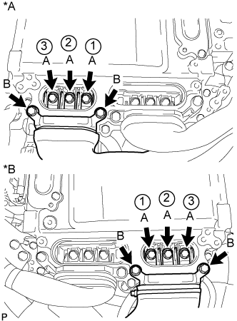
Tighten the 6 bolts in the order shown in the illustration.
- Torque:
- 8.0 N*m { 82 kgf*cm, 71 in.*lbf }
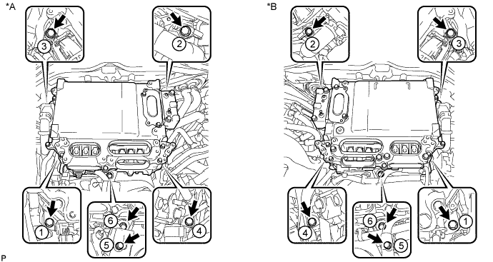
Text in Illustration *A for LHD *B for RHD -
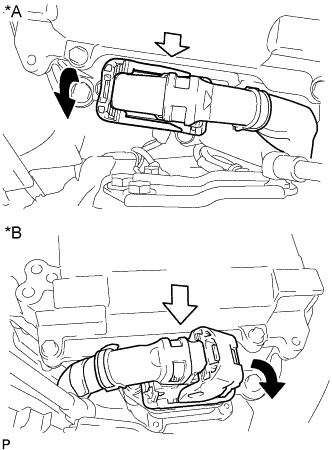
Text in Illustration *A for LHD *B for RHD Connect the connector and lock the connector with the lock lever.
Note
-
Do not allow any foreign objects or water to enter the inverter with converter assembly.
-
Make sure that the connectors are fully engaged.
-
-
-
CONNECT INVERTER BUS-BAR PLATE SUB-ASSEMBLY
-
for LHD:
-
Install the wire harness bracket with the bolt.
- Torque:
- 8.5 N*m { 87 kgf*cm, 75 in.*lbf }
-
Temporarily install the inverter bus-bar plate sub-assembly with the 3 nuts.
-
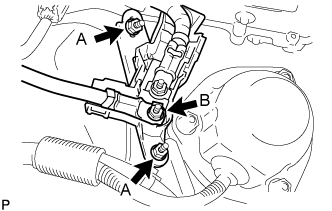
Tighten the 2 nuts labeled A in the illustration.
- Torque:
- 6.9 N*m { 70 kgf*cm, 61 in.*lbf }
-
Tighten the nut labeled B in the illustration.
- Torque:
- 11 N*m { 107 kgf*cm, 8 ft.*lbf }
-
Attach the harness cover.
-
-
for RHD:
-
Attach the 2 claws and install the nut.
- Torque:
- 11 N*m { 107 kgf*cm, 8 ft.*lbf }
-
Install the relay block cover.
-
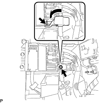
Connect the connector and attach the clamp.
-
-
-
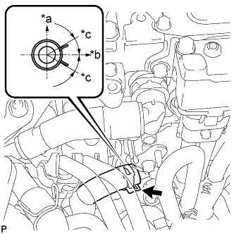
CONNECT NO. 2 INVERTER COOLING INLET HOSE (for RHD)
-
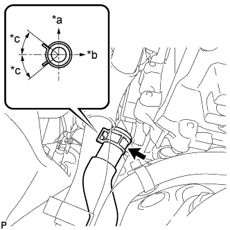
Text in Illustration *a Upper *b LH Side *c 30° Connect the No. 2 inverter cooling inlet hose to the inverter with converter assembly, and slide the clamp to secure the hose.
Note
To prevent foreign matter from entering the cooling system, do not remove the pieces of cloth or plastic bags from the pipes and disconnected hoses.
Tech Tips
Make sure the direction of the hose clamp is as shown in the illustration.
-
-
CONNECT NO. 1 INVERTER COOLING INLET HOSE (for LHD)
-
Text in Illustration *a Upper *b LH Side *c 30° Connect the No. 1 inverter cooling inlet hose to the inverter with converter assembly, and slide the clamp to secure the hose.
Note
To prevent foreign matter from entering the cooling system, do not remove the pieces of cloth or plastic bags from the pipes and disconnected hoses.
Tech Tips
Make sure the direction of the hose clamp is as shown in the illustration.
-
-
INSTALL INVERTER INLET PIPE ASSEMBLY (for RHD)
-
Install the inverter inlet pipe assembly with the bolt and nut to the suspension tower LH.
- Torque:
- 13 N*m { 127 kgf*cm, 9 ft.*lbf }
-
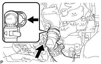
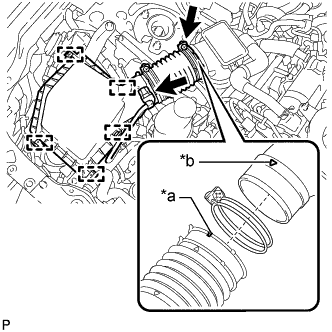
Connect the No. 2 inverter cooling outlet hose to the inverter with converter assembly and lock the hose with the retainer.
Note
-
Insert the retainer until a click sound is heard.
-
Pull on the hose to confirm that the hose is securely connected.
-
If there is foreign matter on the union or the O-ring, clean it with water and finger scouring.
-
To prevent foreign matter from entering the cooling system, do not remove the pieces of cloth or plastic bags from the pipes and disconnected hoses.
-
-
-
INSTALL NO. 1 INVERTER COOLING OUTLET HOSE (for LHD)
-
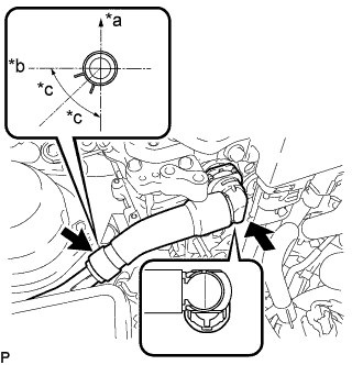
Text in Illustration *a Upper *b RH Side *c 44.5° Install the No. 1 inverter cooling outlet hose to the inverter with converter assembly, lock the hose with the retainer and slide the clamp to secure the hose.
Note
-
Insert the retainer until a click sound is heard.
-
Pull on the hose to confirm that the hose is securely connected.
-
If there is foreign matter on the union or the O-ring, clean it with water and finger scouring.
-
To prevent foreign matter from entering the cooling system, do not remove the pieces of cloth or plastic bags from the pipes and disconnected hoses.
-
-
-
CONNECT FUEL TUBE SUB-ASSEMBLY (for LHD)
-
Подсоедините топливопровод в сборе к топливной рампе (см. стр. Click here).
-
Подсоедините топливопровод в сборе к топливному насосу с уплотнением в сборе (см. стр. Click here).
-
Подсоедините зажим топливопровода № 1 к кронштейну зажима жгута проводов.
-
-
INSTALL CONNECTOR COVER ASSEMBLY
CAUTION:
Wear insulated gloves.
Note
-
Make sure that the interlock is fully engaged.
-
Do not allow any foreign objects or water to enter the inverter with converter assembly.
-
Using an insulated tool, install the connector cover assembly with the 2 bolts.
- Torque:
- 8.0 N*m { 82 kgf*cm, 71 in.*lbf }
-
-
CONNECT MOTOR CABLE
CAUTION:
Wear insulated gloves.
Note
-
Do not damage the terminals, connector housings or inverter with converter assembly when connecting them.
-
Do not touch the connector waterproofing rubber or terminals.
-
Do not allow any foreign objects or water to enter the inverter with converter assembly.
-
Temporarily install the motor cable with the 5 bolts.
-
Text in Illustration *A for LHD *B for RHD Using an insulated tool, tighten the 3 bolts labeled A in the illustration.
- Torque:
- 8.0 N*m { 82 kgf*cm, 71 in.*lbf }
Note
-
The connector should be connected securely.
-
The bolts should be tightened securely.
-
Tighten the bolts in the order shown in the illustration.
-
Using an insulated tool, tighten the 2 bolts labeled B in the illustration.
- Torque:
- 8.0 N*m { 82 kgf*cm, 71 in.*lbf }
Note
-
The connector should be connected securely.
-
The bolts should be tightened securely.
-
-
CONNECT GENERATOR CABLE
CAUTION:
Wear insulated gloves.
Note
-
Do not damage the terminals, connector housings or inverter with converter assembly when connecting them.
-
Do not touch the connector waterproofing rubber or terminals.
-
Do not allow any foreign objects or water to enter the inverter with converter assembly.
-
Temporarily install the generator cable with the 5 bolts.
-
Text in Illustration *A for LHD *B for RHD Using an insulated tool, tighten the 3 bolts labeled A in the illustration.
- Torque:
- 8.0 N*m { 82 kgf*cm, 71 in.*lbf }
Note
-
The connector should be connected securely.
-
The bolts should be tightened securely.
-
Tighten the bolts in the order shown in the illustration.
-
Using an insulated tool, tighten the 2 bolts labeled B in the illustration.
- Torque:
- 8.0 N*m { 82 kgf*cm, 71 in.*lbf }
Note
-
The connector should be connected securely.
-
The bolts should be tightened securely.
-
-
INSTALL INVERTER TERMINAL COVER
CAUTION:
Wear insulated gloves.
-
for Type A:
-
Using an insulated tool, install the inverter terminal cover with the 2 bolts.
- Torque:
- 8.0 N*m { 82 kgf*cm, 71 in.*lbf }
Note
-
Do not touch the inverter terminal cover waterproofing rubber.
-
Visually confirm that the inverter terminal cover waterproofing rubber is securely installed before installing the inverter terminal cover.
-
Press down on the inverter terminal cover with both hands to securely connect the interlock.
-
-
for Type B:
-
Using an insulated tool, install the inverter terminal cover with the 3 bolts.
- Torque:
- 8.0 N*m { 82 kgf*cm, 71 in.*lbf }
Note
-
Do not touch the inverter terminal cover waterproofing rubber.
-
Visually confirm that the inverter terminal cover waterproofing rubber is securely installed before installing the inverter terminal cover.
-
Press down on the inverter terminal cover with both hands to securely connect the interlock.
-
-
-
INSTALL INVERTER MOTOR CABLE BRACKET ASSEMBLY
-
Install the inverter motor cable bracket assembly with the 2 bolts.
- Torque:
- 8.0 N*m { 82 kgf*cm, 71 in.*lbf }
-
Attach the 2 clamps to the inverter motor cable bracket assembly.
-
-
INSTALL AIR CLEANER HOSE ASSEMBLY (for LHD)
-
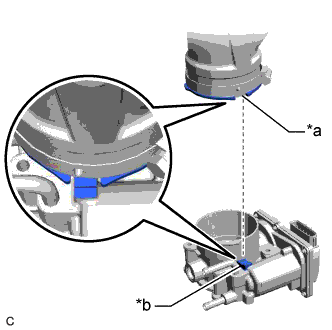
Text in Illustration *a Cutout *b Protrusion Align the cutout of the air cleaner hose assembly with the protrusion of the throttle body with motor assembly, and install the air cleaner hose assembly.
-
Tighten the hose clamp.
- Torque:
- 4.0 N*m { 41 kgf*cm, 35 in.*lbf }
Note
Fit the protrusion on the air cleaner hose assembly into the hole of the hose clamp.
-
Connect the ventilation hose to the throttle body with motor assembly, and slide the clamp to secure the hose.
-
-
INSTALL AIR CLEANER CAP WITH NO. 2 AIR CLEANER HOSE (for LHD)
-
Text in Illustration *a Groove *b Matchmark Connect the air cleaner cap with No. 2 air cleaner hose to the air cleaner hose assembly.
Tech Tips
Make sure the direction of the installation is as shown in the illustration.
-
Attach the 4 clamps to install the air cleaner cap with No. 2 air cleaner hose.
-
Tighten the hose clamp.
- Torque:
- 4.0 N*m { 41 kgf*cm, 35 in.*lbf }
-
Connect the wire harness clamp to the air cleaner cap with No. 2 air cleaner hose.
-
Connect the mass air flow meter sub-assembly connector.
-
-
INSTALL SERVICE PLUG GRIP
-
CONNECT CABLE TO AUXILIARY NEGATIVE BATTERY TERMINAL
Note
When disconnecting the cable some systems need to be initialized after the cable is reconnected Click here.
-
Connect cable to the auxiliary battery positive (+) terminal with the nut.
- Torque:
- 6.8 N*m { 69 kgf*cm, 60 in.*lbf }
-
Install the terminal cover.
-
Connect cable to the auxiliary battery negative (-) terminal.
- Torque:
- 5.5 N*m { 56 kgf*cm, 49 in.*lbf }
-
-
CONNECT INVERTER COOLING HOSE ASSEMBLY (for RHD)
-
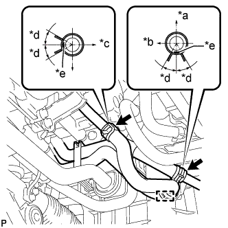
Text in Illustration *a Upper *b Front Side *c LH Side *d 30° *e Paint Mark Connect the 2 ends of the inverter cooling hoses to the inverter cooling pipes and secure the hoses with the 2 hose clamps.
Tech Tips
Make sure that the clamps are positioned as shown in the illustration.
-
Attach the inverter cooling hose clamp to the inverter cooling pipe assembly.
-
-
ADD COOLANT (for Inverter)
Note
-
Do not reuse the drained coolant because it may contain foreign objects.
-
If the vehicle is driven with air in the inverter cooling system, damage may occur and the following DTCs may be stored.
DTC Code Detection Item P0A01-726 Motor Electronics Coolant Temperature Sensor Circuit Range / Performance P0A04-725 Motor Electronics Coolant Temperature Sensor Circuit Intermittent P0A08-264 DC / DC Converter Status Circuit P0A78-284 Drive Motor "A" Inverter Performance P0A78-286 Drive Motor "A" Inverter Performance P0A7A-322 Generator Inverter Performance P0A7A-324 Generator Inverter Performance P0A93-346 Inverter Cooling System Performance P0A94-553 DC / DC Converter Performance P0A94-557 DC / DC Converter Performance P0AEE-277 Motor Inverter Temperature Sensor "A" Circuit Range / Performance P0AF1-276 Drive Motor Inverter Temperature Sensor "A" Circuit Intermittent / Erratic P0BCD-315 Generator Inverter Temperature Sensor Circuit Range / Performance P0BD0-314 Generator Inverter Temperature Sensor Circuit Range / Erratic P0C39-626 DC / DC Converter Temperature Sensor "A" Range / Performance P0C3C-625 DC / DC Converter Temperature Sensor "A" Intermittent / Erratic P0C3E-628 DC / DC Converter Temperature Sensor "B" Range / Performance P0C41-627 DC / DC Converter Temperature Sensor "B" Intermittent / Erratic P0C73-776 Motor Electronics Coolant Pump "A" Control Performance
-
Tighten the drain cock plug.
-
Slowly pour coolant into the reservoir tank until it reaches the FULL line.
Standard Capacity Item Specified Condition for LHD 2.1 liters (2.2 US qts, 1.8 Imp. qts) for RHD 2.3 liters (2.4 US qts, 2.0 Imp. qts) Note
To prevent foreign matter such as dust or dirt from entering the cooling system, make sure to confirm that the container used to add coolant is clean and free of foreign matter such as dust or dirt.
-
When using the GTS:
-
Connect the GTS to the DLC3.
-
Turn the power switch on (IG).
-
Enter the following menus: Powertrain / Hybrid Control / Active Test / Activate the Water Pump.
-
Keep the coolant at the FULL line in the reservoir tank to compensate for the drop in coolant level when the air bleeds.
Standard Air bleeding from the inverter cooling system is completed when the noise made by the inverter water pump assembly becomes smaller and the circulation of coolant in the reservoir tank improves. Tech Tips
-
If free spinning of the inverter water pump is detected for approximately 5 seconds, failsafe control will be activated to suspend the operation of the pump for approximately 15 seconds and resume operation for approximately 4 seconds repeatedly. Operation of the inverter water pump will return to normal if coolant is added.
-
Loud noise made by the inverter water pump and poor circulation of coolant in the reservoir tank indicates that there is air in the cooling system.
-
-
-
When not using the GTS:
-
Turn the power switch on (READY). [*1]
-
Turn the power switch off and add coolant to the FULL line because the coolant level drops as the air bleeds. [*2]
Note
-
Be sure to turn the power switch off before adding SLLC.
-
Do not work on the components in the engine compartment while the vehicle is in the READY-on state because the engine is in intermittent operation.
-
-
Repeat steps [*1] and [*2] until air bleeding from the cooling system is completed.
Standard Air bleeding from the inverter cooling system is completed when the noise made by the inverter water pump assembly becomes smaller and the circulation of coolant in the reservoir tank improves. Tech Tips
Loud noise made by the inverter water pump and poor circulation of coolant in the reservoir tank indicates that there is air in the cooling system.
-
-
After the air is completely bled from the cooling system, tighten the reservoir tank cap.
-
Add coolant to the FULL line of the reservoir tank.
-
-
INSPECT FOR COOLANT LEAK (for Inverter)
-
Remove the reservoir tank cap (for inverter).
CAUTION:
To avoid the danger of being burned, do not remove the reservoir tank cap while the coolant for the inverter is still hot.
-
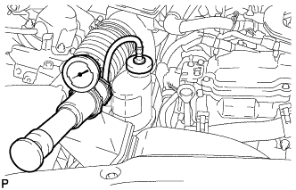
Install the radiator cap tester.
-
Pump the radiator cap tester to 137 kPa (1.4 kgf/ cm2, 20 psi), and then check that the pressure does not drop.
Tech Tips
If the pressure drops, check the hoses, radiator, water pump, inverter with converter, and hybrid vehicle transaxle assembly for leaks.
-
Reinstall the reservoir tank cap (for inverter).
-
-
INSTALL NO. 1 ENGINE COVER SUB-ASSEMBLY
-
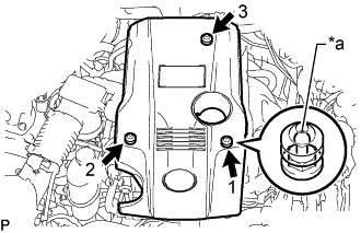
Обозначения на рисунке *a Наконечник (круглая часть) Установите крышку двигателя № 1 в сборе и введите в зацепление 3 фиксатора в порядке, показанном на рисунке.
Note
-
Надежно присоедините фиксаторы.
-
Если закреплять фиксаторы с усилием или подвергать их ударам, они могут получить повреждения.
-
-
-
INSTALL INVERTER COVER
-
Attach the 2 inverter cover claws to the inverter with converter. Then attach the inverter cover with the clip.
-
-
INSTALL ENGINE UNDER COVER
-
Установите защиту картера двигателя и закрепите ее 13 винтами и 3 фиксаторами.
-
-
INSTALL NO. 1 AIR CLEANER INLET
-
Установите входной патрубок воздушного фильтра № 1 и закрепите его болтом.
- Torque:
- 5,0 Н*м { 51 кгс*см, 44 фунт-сила-дюйма }
-
-
INSTALL COOL AIR INTAKE DUCT SEAL
-
Установите сальник впускного воздухопровода холодного воздуха и закрепите его 7 фиксаторами.
-
-
INSTALL ENGINE ROOM SIDE COVER
-
Установите боковую крышку моторного отсека и закрепите ее 4 фиксаторами.
-
-
INSTALL LUGGAGE COMPARTMENT TRIM COVER LH
-
Установите левую облицовочную накладку багажного отделения.
-
-
INSTALL LUGGAGE COMPARTMENT FLOOR MAT
-
Установите напольный коврик багажного отделения.
-