СИСТЕМА УПРАВЛЕНИЯ ГИБРИДНОЙ СИСТЕМОЙ, Diagnostic DTC:P0AEE-277, P0AF1-276
| DTC Code | DTC Name |
|---|---|
| P0AEE-277 | Motor Inverter Temperature Sensor "A" Circuit Range / Performance |
| P0AF1-276 | Drive Motor Inverter Temperature Sensor "A" Circuit Intermittent / Erratic |
DESCRIPTION
The MG ECU, which is built into in the inverter with converter assembly, detects the temperature of the motor inverter using the temperature sensor built into the motor inverter. If necessary, the MG ECU will limit inverter output to help prevent motor inverter overheating. The power management control ECU also detects malfunctions in the sensor based on the temperature sensor values. The inverter with converter assembly detects malfunctions in the motor inverter temperature sensor and its wiring.
| DTC No. | DTC Detection Condition | Trouble Area |
|---|---|---|
| P0AEE-277 | Motor inverter temperature calculated by the power management control ECU is different from the actual temperature for 10 seconds or more, and the motor inverter temperature is too high. (1 trip detection logic) |
|
| P0AF1-276 | Sudden change in motor inverter temperature sensor output or hunting: Motor inverter temperature is high and either of the following conditions is met:
(1 trip detection logic) |
|
Tech Tips
*: If only DTC P0AF1-276 is output, a temperature sensor malfunction is more likely to be the cause than a sudden change in actual temperature.
| DTC No. | Data List |
|---|---|
| P0AEE-277 |
|
| P0AF1-276 |
INSPECTION PROCEDURE
CAUTION:
-
Before inspecting the high-voltage system or disconnecting the low voltage connector of the inverter with converter assembly, take safety precautions such as wearing insulated gloves and removing the service plug grip to prevent electrical shocks. After removing the service plug grip, put it in your pocket to prevent other technicians from accidentally reconnecting it while you are working on the high-voltage system.
-
After removing the service plug grip, wait for at least 10 minutes before touching any of the high-voltage connectors or terminals. After waiting for 10 minutes, check the voltage at the terminals in the inspection point in the inverter with converter assembly. The voltage should be 0 V before beginning work Click here.
Tech Tips
Waiting for at least 10 minutes is required to discharge the high-voltage capacitor inside the inverter with converter assembly.
Note
After turning the power switch off, waiting time may be required before disconnecting the cable from the negative (-) auxiliary battery terminal. Therefore, make sure to read the disconnecting the cable from the negative (-) auxiliary battery terminal notices before proceeding with work Click here.
Tech Tips
After the repair, clear the DTCs and perform the following procedure to check that DTCs are not output.
-
Turn the power switch on (READY) and wait for 90 seconds or more.
-
Drive the vehicle for approximately 10 minutes referring to the following freeze frame data or Data List items: "Vehicle Spd".
PROCEDURE
-
CHECK DTC OUTPUT (HYBRID CONTROL)
-
Connect the GTS to the DLC3.
-
Turn the power switch on (IG).
-
Enter the following menus: Powertrain / Hybrid Control / Trouble Codes.
-
Check for DTCs.
Result Result Proceed to P0AEE-277 or P0AF1-276 only is output, or DTCs except the ones in the table below are also output. A Any of the following DTCs are also output. B DTC No. Relevant Diagnosis P0A93-346 Inverter Cooling System Performance P0C73-776 Motor Electronics Coolant Pump "A" Control Performance P314A-828 Inverter Coolant Pump Speed Signal Tech Tips
P0AEE-277 or P0AF1-276 may be stored due to a malfunction which also causes DTCs in the preceding table to be stored. In this case, first troubleshoot the output DTCs in the preceding table. Then, perform a test to attempt to reproduce the problems, and check that no DTCs are output.
-
Turn the power switch off.
B 
GO TO DTC CHART (HYBRID CONTROL SYSTEM) Click here
A 
-
-
CHECK CONNECTOR CONNECTION CONDITION (INVERTER WITH CONVERTER ASSEMBLY CONNECTOR)
CAUTION:
Be sure to wear insulated gloves.
-
Check that the service plug grip is not installed.
Note
After removing the service plug grip, do not turn the power switch on (READY), unless instructed by the repair manual because this may cause a malfunction.
-
Check connection condition of the low voltage connector of the inverter with converter assembly and the contact pressure of each terminal. Check the terminals for deformation, and check the connector for water ingress and foreign matter Click here.
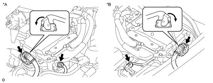
Text in Illustration *A for LHD *B for RHD Note
Before disconnecting the connector, confirm that it is properly connected by checking that the locking claws are engaged and that the connector does not pull out.
OK - The connector is connected securely. - The terminals are not deformed and are connected securely. - No water or foreign matter in the connector. Result Result Proceed to OK A NG (The connector is not connected securely.) B NG (The terminals are not making secure contact or are deformed, or water or foreign matter exists in the connector.) C Tech Tips
When connecting the connector, insert it with the locking lever in the raised position. Rotate the lever downward and make sure that the connector is pulled into its socket. When the locking lever is in its fully closed position, a click will be heard as its locking claws engage. After the click is heard, pull up on the connector to confirm that it is properly connected.
B
CONNECT SECURELY
C
REPAIR OR REPLACE HARNESS OR CONNECTOR
A
-
-
CHECK QUANTITY OF HV COOLANT
-
Проверьте уровень охлаждающей жидкости гибридной системы в расширительном бачке инвертора.
-
Проверьте, нет ли утечек охлаждающей жидкости гибридной системы.
Результат Результат Перейти к Утечки не обнаружены, и уровень охлаждающей жидкости в расширительном бачке инвертора выше нижней отметки. А Утечки не обнаружены, и уровень охлаждающей жидкости в расширительном бачке инвертора ниже нижней отметки. B Обнаружены утечки охлаждающей жидкости гибридной системы. C Note
Насос системы охлаждения инвертора с электродвигателем в сборе имеет функцию защиты, которая активируется в случае утечки охлаждающей жидкости гибридной системы. Таким образом, нет необходимости заменять насос системы охлаждения инвертора с электродвигателем в сборе, если только причиной утечки охлаждающей жидкости гибридной системы не является насос системы охлаждения инвертора с электродвигателем в сборе.
Tech Tips
После устранения утечек и добавления охлаждающей жидкости гибридной системы выполните испытания Active Test "Activate the (Inverter) Water Pump" (включение насоса системы охлаждения инвертора) (испытание из раздела HV) и "Control the Electric Cooling Fan" (управление электрическим вентилятором системы охлаждения) (испытание из раздела Engine), и убедитесь в отсутствии неисправностей.
B
ADD HV COOLANT
C
INSPECT FOR HV COOLANT LEAK AND ADD HV COOLANT
A
-
-
CHECK COOLANT HOSE
-
Убедитесь, что шланги системы охлаждения не перегнуты и не засорены.
NG
REPAIR OR REPLACE COOLANT HOSE
OK
-
-
PERFORM ACTIVE TEST USING GTS (CONTROL THE ELECTRIC COOLING FAN)
-
Подключите GTS к DLC3.
-
Включите питание (IG).
-
Войдите в следующие меню: Powertrain / Engine and ECT / Active Test / Control the Electric Cooling Fan.
-
Выполните испытание Active Test "Control the Electric Cooling Fan" (управление электрическим вентилятором системы охлаждения).
OK Вентилятор системы охлаждения вращается. -
Выключите питание.
NG
CHECK COOLING FAN SYSTEM Click here
OK
-
-
CHECK HV COOLANT (CHECK FOR CONDITIONS THAT MAY HAVE CAUSED FREEZING)
-
Подключите GTS к DLC3.
-
Включите питание (IG).
-
Войдите в следующие меню: Powertrain / Hybrid Control / Trouble Codes.
-
С помощью GTS считайте значение "Ambient Temperature" в данных фиксированного набора параметров.
-
Убедитесь, что значение параметра "Ambient Temperature" из фиксированного набора параметров ниже температуры замерзания охлаждающей жидкости гибридной системы.
Результат Результат Перейти К Значение "Ambient Temperature" ниже температуры замерзания охлаждающей жидкости гибридной системы. А Значение "Ambient Temperature" превышает температуру замерзания охлаждающей жидкости гибридной системы. B Tech Tips
-
Охлаждающая жидкость гибридной системы (SLLC) с концентрацией 30% замерзает при температуре -15°C (5°F), а с концентрацией 50% – при температуре -35°C (-31°F).
-
При замерзании охлаждающей жидкости гибридной системы в радиаторе гибридной системы или насосе системы охлаждения гибридной системы температура охлаждающей жидкости в преобразователе-инверторе в сборе возрастает из-за прекращения циркуляции охлаждающей жидкости. В результате может быть зарегистрирован код DTC.
-
DTC сохранятся, если крыльчатка насоса системы охлаждения не может вращаться из-за замерзания охлаждающей жидкости гибридной системы.
-
Если DTC выводятся вследствие замерзания LLC, признак неисправности воспроизвести невозможно. Проверьте данные о замене LLC и выясните, замерзала ли LLC, исходя из температуры окружающего воздуха в момент сохранения кодов DTC.
-
-
Выключите питание.
B
REPLACE INVERTER WITH CONVERTER ASSEMBLY Click here
A
-
-
REPLACE HV COOLANT
-
Замените охлаждающую жидкость гибридной системы охлаждающей жидкостью с концентрацией (температурой замерзания), соответствующей условиям эксплуатации автомобиля (см. стр. Click here).
NEXT 
COMPLETED
-