HAZARD WARNING SWITCH INSPECTION
PROCEDURE
-
INSPECT CLOCK ASSEMBLY
-
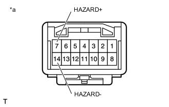
Text in Illustration *a Component without harness connected
(Clock Assembly)
Measure the resistance according to the value(s) in the table below.
Standard Resistance Tester Connection Switch Condition Specified Condition 7 (HAZARD+) - 14 (HAZARD-) Hazard warning signal switch off 10 kΩ or higher 7 (HAZARD+) - 14 (HAZARD-) Hazard warning signal switch on Below 1 Ω -
Apply battery voltage to the connector and check the LED illumination condition.
OK Condition Specified Condition Battery positive (+) → 9
Battery negative (-) → 13
LED illuminates
-