LIGHTING SYSTEM Hazard Warning Switch Circuit
DESCRIPTION
the low beam headlights do not illuminate, or a communication malfunction is detected between the headlight assembly and main body ECU (multiplex network body ECU).
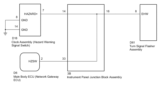
WIRING DIAGRAM
-
w/ side turn signal light
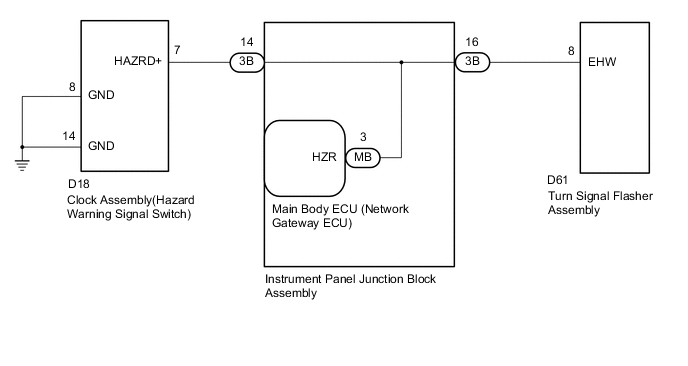
-
w/o side turn signal light
PROCEDURE
-
CHECK VEHICLE TYPE
-
Check vehicle type.
Result Result Proceed to w/ side turn signal light A w/o side turn signal light B
B 
READ VALUE USING GTS (HAZARD SWITCH) Click here
A 
-
-
READ VALUE USING GTS (HAZARD SWITCH)
-
Connect the GTS to the DLC3.
-
Turn the ignition switch to ON.
-
Turn the GTS on.
-
Enter the following menus: Body / Main Body / Data List.
-
Read the Data List according to the display on the GTS.
Main Body Tester Display Measurement Item/Range Normal Condition Diagnostic Note Hazard Switch Hazard warning signal switch signal ON or OFF ON: Hazard switch on
OFF: Hazard switch off
- OK Normal conditions listed above are displayed.
NG
CHECK HARNESS AND CONNECTOR (INSTRUMENT PANEL JUNCTION BLOCK ASSEMBLY - CLOCK ASSEMBLY (HAZARD WARNING SIGNAL SWITCH) ) Click here
OK
-
-
CHECK HARNESS AND CONNECTOR (INSTRUMENT PANEL JUNCTION BLOCK ASSEMBLY - TURN SIGNAL FLASHER ASSEMBLY)
-
Disconnect the 3B instrument panel junction block assembly connector.
-
Disconnect the D61 turn signal flasher assembly connector.
-
Measure the resistance according to the value(s) in the table below.
Standard Resistance Tester Connection Condition Specified Condition 3B-16 - D61-8 (EHW) Always Below 1 Ω 3B-16 or D61-8 (EHW) - Body ground Always 10 kΩ or higher
NG 
REPAIR OR REPLACE HARNESS OR CONNECTOR
OK
-
-
INSPECT INSTRUMENT PANEL JUNCTION BLOCK ASSEMBLY
-
Remove the instrument panel junction block assembly.
-
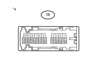
Text in Illustration *a Component without harness connected
(Instrument Panel Junction Block Assembly)
Remove the main body ECU (network gateway ECU) from the instrument panel junction block assembly.
-
Measure the resistance according to the value(s) in the table below.
Standard Resistance Tester Connection Condition Specified Condition 3B-14 - 3B-16 Always Below 1 Ω
OK
REPAIR TURN SIGNAL FLASHER ASSEMBLY Click here
NG
REPAIR INSTRUMENT PANEL JUNCTION BLOCK ASSEMBLY
-
-
CHECK HARNESS AND CONNECTOR (INSTRUMENT PANEL JUNCTION BLOCK ASSEMBLY - CLOCK ASSEMBLY (HAZARD WARNING SIGNAL SWITCH) )
-
Disconnect the 3B instrument panel junction block assembly connector.
-
Disconnect the D18 clock assembly (hazard warning signal switch) connector.
-
Measure the resistance according to the value(s) in the table below.
Standard Resistance Tester Connection Condition Specified Condition 3B-14 - D18-7 Always Below 1 Ω D18-8 - Body ground Always Below 1 Ω D18-14 - Body ground Always Below 1 Ω 3B-14 or D18-7 - Body ground Always 10 kΩ or higher
NG
REPAIR OR REPLACE HARNESS OR CONNECTOR
OK
-
-
INSPECT CLOCK ASSEMBLY (HAZARD WARNING SIGNAL SWITCH)
-
Remove the clock assembly (hazard warning signal switch) Click here.
-
Inspect the clock assembly (hazard warning signal switch) Click here.
NG
REPAIR CLOCK ASSEMBLY (HAZARD WARNING SIGNAL SWITCH) Click here
OK
-
-
INSPECT INSTRUMENT PANEL JUNCTION BLOCK ASSEMBLY
-
Remove the instrument panel junction block assembly.
-
Remove the main body ECU (network gateway ECU) from the instrument panel junction block assembly.
-
Measure the resistance according to the value(s) in the table below.
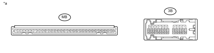
Standard Resistance Tester Connection Condition Specified Condition 3B-16 - MB-3 Always Below 1 Ω Text in Illustration *a Component without harness connected
(Instrument Panel Junction Block Assembly)
- -
OK
REPAIR MAIN BODY ECU (NETWORK GATEWAY ECU)
NG
REPAIR INSTRUMENT PANEL JUNCTION BLOCK ASSEMBLY
-
-
READ VALUE USING GTS (HAZARD SWITCH)
-
Connect the GTS to the DLC3.
-
Turn the ignition switch to ON.
-
Turn the GTS on.
-
Enter the following menus: Body / Main Body / Data List.
-
Read the Data List according to the display on the GTS.
Main Body Tester Display Measurement Item/Range Normal Condition Diagnostic Note Hazard Switch Hazard warning signal switch signal ON or OFF ON: Hazard switch on
OFF: Hazard switch off
- OK Normal conditions listed above are displayed.
NG
CHECK HARNESS AND CONNECTOR Click here
OK
-
-
CHECK HARNESS AND CONNECTOR (INSTRUMENT PANEL JUNCTION BLOCK ASSEMBLY - TURN SIGNAL FLASHER ASSEMBLY)
-
Disconnect the 3B instrument panel junction block assembly connector.
-
Disconnect the D61 turn signal flasher assembly connector.
-
Measure the resistance according to the value(s) in the table below.
Standard Resistance Tester Connection Condition Specified Condition 3B-16 - D61-8 (EHW) Always Below 1 Ω 3B-16 or D61-8 (EHW) - Body ground Always 10 kΩ or higher
NG
REPAIR OR REPLACE HARNESS OR CONNECTOR
OK
-
-
INSPECT INSTRUMENT PANEL JUNCTION BLOCK ASSEMBLY
-
Remove the instrument panel junction block assembly.
-
Text in Illustration *a Component without harness connected
(Instrument Panel Junction Block Assembly)
Remove the main body ECU (network gateway ECU) from the instrument panel junction block assembly.
-
Measure the resistance according to the value(s) in the table below.
Standard Resistance Tester Connection Condition Specified Condition 3B-14 - 3B-16 Always Below 1 Ω
OK
REPAIR TURN SIGNAL FLASHER ASSEMBLY Click here
NG
REPAIR INSTRUMENT PANEL JUNCTION BLOCK ASSEMBLY
-
-
CHECK HARNESS AND CONNECTOR
-
Disconnect the 3B instrument panel junction block assembly connector.
-
Disconnect the D18 clock assembly (hazard warning signal switch) connector.
-
Measure the resistance according to the value(s) in the table below.
Standard Resistance Tester Connection Condition Specified Condition 3B-14 - D18-7 (HAZRD+) Always Below 1 Ω D18-8 (GND) - Body ground Always Below 1 Ω D18-14 (GND) - Body ground Always Below 1 Ω 3B-14 or D18-7 - Body ground Always 10 kΩ or higher
NG
REPAIR OR REPLACE HARNESS OR CONNECTOR
OK
-
-
INSPECT CLOCK ASSEMBLY (HAZARD WARNING SIGNAL SWITCH)
-
Remove the clock assembly (hazard warning signal switch) Click here.
-
Inspect the clock assembly (hazard warning signal switch) Click here.
NG
REPAIR CLOCK ASSEMBLY (HAZARD WARNING SIGNAL SWITCH) Click here
OK
-
-
INSPECT INSTRUMENT PANEL JUNCTION BLOCK ASSEMBLY
-
Remove the instrument panel junction block assembly.
-
Text in Illustration *a Component without harness connected
(Instrument Panel Junction Block Assembly)
Remove the main body ECU (network gateway ECU) from the instrument panel junction block assembly.
-
Measure the resistance according to the value(s) in the table below.
Standard Resistance Tester Connection Condition Specified Condition 3B-14 - 3B-33 Always Below 1 Ω
OK
REPAIR MAIN BODY ECU (NETWORK GATEWAY ECU)
NG
REPAIR INSTRUMENT PANEL JUNCTION BLOCK ASSEMBLY
-