LIGHTING SYSTEM Rear Fog Light Circuit
DESCRIPTION
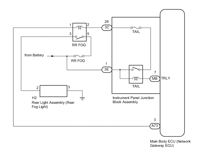
The main body ECU (network gateway ECU) receives headlight dimmer switch assembly information signals, and illuminates the rear fog light.
WIRING DIAGRAM
CAUTION / NOTICE / HINT
Tech Tips
Inspect the fuses and bulbs for circuits related to this system before performing the following inspection procedure.
PROCEDURE
-
CHECK OPERATION (TAILLIGHT)
-
Check the operation of the taillight.
OK The taillight operates normally.
NG 
GO TO TAILLIGHT Click here
OK 
-
-
PERFORM ACTIVE TEST USING GTS
-
Connect the GTS to the DLC3.
-
Turn the ignition switch to ON.
-
Turn the GTS on.
-
Enter the following menus: Body Electrical / Main Body / Active Test.
-
Check that the relay operates.
Main Body Tester Display Test Part Control Range Diagnostic Note Rear Fog Light Relay Rear fog light relay ON/OFF Light control switch is in TAIL position OK Rear fog light relay operates (Rear fog lights come on).
OK
REPLACE MAIN BODY ECU (NETWORK GATEWAY ECU) Click here
NG
-
-
INSPECT RR FOG RELAY
-
Remove the RR FOG relay from the engine room relay block.
-
Inspect the RR FOG relay Click here.
NG
REPLACE RR FOG RELAY
OK
-
-
INSPECT REAR FOG LIGHT BULB (REAR LIGHT ASSEMBLY)
-
Remove the rear fog light bulb Click here.
-
Inspect the rear fog light bulb Click here.
NG
REPLACE REAR FOG LIGHT BULB Click here
OK
-
-
CHECK HARNESS AND CONNECTOR (BATTERY - RR FOG RELAY)
-
Measure the voltage according to the value(s) in the table below.
Standard Voltage Tester Connection Switch Condition Specified Condition Relay terminal 2 - Body ground Light control switch off → tail Below 1 V → 11 to 14 V Relay terminal 5 - Body ground Always 11 to 14 V
NG 
INSPECT INSTRUMENT PANEL JUNCTION BLOCK ASSEMBLY Click here
OK
-
-
CHECK HARNESS AND CONNECTOR (RR FOG RELAY - REAR LIGHT ASSEMBLY)
-
Disconnect the H2 rear light assembly connector.
-
Measure the resistance according to the value(s) in the table below.
Standard Resistance (Check for Open) Tester Connection Condition Specified Condition Relay terminal 3 - H2-2 Light control switch off → tail Below 1 Ω Standard Resistance (Check for Short) Tester Connection Condition Specified Condition Relay terminal 3 - Body ground Always 10 kΩ or higher
NG
REPAIR OR REPLACE HARNESS OR CONNECTOR
OK
-
-
CHECK HARNESS AND CONNECTOR (RR FOG RELAY - INSTRUMENT PANEL JUNCTION BLOCK ASSEMBLY)
-
Disconnect the A73 instrument panel junction block assembly connector.
-
Measure the resistance according to the value(s) in the table below.
Standard Resistance (Check for Open) Tester Connection Condition Specified Condition Relay terminal 1 - A73-3 Always Below 1 Ω Standard Resistance (Check for Short) Tester Connection Condition Specified Condition Relay terminal 1 - Body ground Always 10 kΩ or higher
NG
REPAIR OR REPLACE HARNESS OR CONNECTOR
OK
-
-
INSPECT INSTRUMENT PANEL JUNCTION BLOCK ASSEMBLY
-
Remove the instrument panel junction block assembly Click here.
-
Remove the main body ECU (network gateway ECU) from the instrument panel junction block assembly.
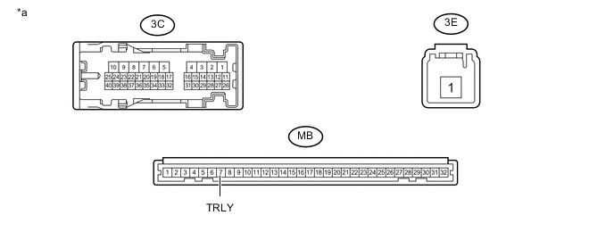
Text in Illustration *a Component without harness connected
(Instrument Panel Junction Block Assembly)
- - -
Measure the voltage according to the value(s) in the table below.
Standard Voltage Tester Connection Condition Specified Condition 3C-26 - Battery negative (-) terminal Connect a positive (+) lead from the battery → 3E-1
Connect a negative (-) lead from the battery → MB-7 (TRLY)
11 to 14 V
OK
REPLACE MAIN BODY ECU (NETWORK GATEWAY ECU) Click here
NG
REPLACE INSTRUMENT PANEL JUNCTION BLOCK ASSEMBLY Click here
-