LIGHTING SYSTEM TERMINALS OF ECU
-
CHECK MAIN BODY ECU (NETWORK GATEWAY ECU)
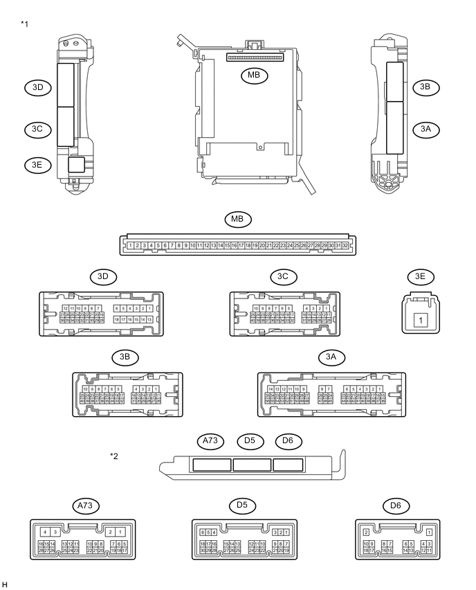
Text in Illustration *1 Instrument Panel Junction Block Assembly *2 Main Body ECU (Network Gateway ECU)
-
Remove the main body ECU (network gateway ECU) from the instrument panel junction block assembly.
-
Disconnect the A73 and D6 main body ECU (network gateway ECU) connectors.
-
Measure the resistance and voltage according to the value(s) in the table below.
Terminal No. Wiring Color Terminal Description Condition Specified Condition A73-4(GND) - Body ground B-Y - Body ground Ground Always Below 1 Ω D6-1(GND) - Body ground B - Body ground Ground Always Below 1 Ω 3C-4 - Body ground None - Body ground Ignition switch power supply Ignition switch ON 11 to 14 V Ignition switch off Below 1 V 3C-7 - Body ground None - Body ground Battery power supply Always 11 to 14 V 3E-1 - Body ground None - Body ground Battery power supply Always 11 to 14 V If the result is not as specified, there may be a malfunction in the wire harness.
-
Reconnect the instrument panel junction block assembly and main body ECU (network gateway ECU) connectors.
-
Measure the resistance according to the value(s) in the table below.
Standard Resistance Terminal No. (Symbol) Wiring Color Terminal Description Condition Specified Condition D6-13 (CLTE)* - Body ground G - Body ground Automatic light control sensor ground Always Below 1 Ω
-
*: w/ Automatic Light Control System
-
-
Measure the voltage or check for pulses according to the value(s) in the table below.
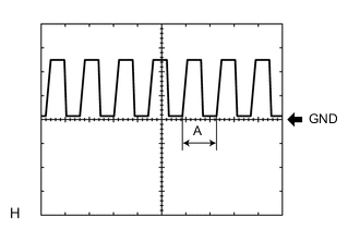
Terminal No. (Symbol) Wiring Color Terminal Description Condition Specified Condition D5-26 (RFOG)*1 - Body ground Y - Body ground Rear fog light switch signal Rear fog light switch on Below 1 V Rear fog light switch off Pulse generation
(See waveform 2 or 3)
MB-21 (HU) - Body ground None - Body ground Dimmer switch high signal Dimmer switch in high position Below 1 V Dimmer switch in low position 11 to 14 V MB-18 (HF) - Body ground None - Body ground Dimmer switch high flash signal Dimmer switch in high flash position Below 1 V Dimmer switch not in high flash position Pulse generation
(See waveform 2 or 3)
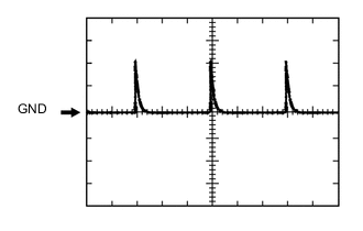
D6-15 (CLTB)*2 - Body ground R - Body ground Automatic light control sensor power supply Ignition switch ON 11 to 14 V D6-14 (CLTS)*2 - Body ground LG - Body ground Automatic light control sensor signal Ignition switch off Below 1 V Automatic light control system operates Pulse generation
(See waveform 1)
D5-24 (FFOG)*3 - Body ground W - Body ground Front fog light switch signal Front fog light switch on Below 1 V Front fog light switch off 11 to 14 V D5-23 (A)*2 - Body ground SB - Body ground Light control switch AUTO signal Light control switch in AUTO position Below 1 V Light control switch not in AUTO position Pulse generation
(See waveform 2 or 3)
D5-2 (HEAD1) - Body ground W - Body ground Light control switch head signal Light control switch in head position Below 1 V Light control switch not in head position 11 to 14 V D5-25 (TAIL) - Body ground) BE - Body ground Light control switch tail signal Light control switch in tail or head position Below 1 V Light control switch in neither tail nor head position 11 to 14 V MB-30 (FFGO)*3 - Body ground None - Body ground Front fog relay drive output Light control switch in tail and front fog light switch on Below 1 V Light control switch in tail and front fog light switch off 11 to 14 V A73-2 (HRLY) - Body ground L - Body ground Headlight relay drive output Light control switch in head Below 1 V Light control switch not in head 11 to 14 V A73-11 (DIM) - Body ground G - Body ground Dimmer relay drive output Dimmer switch in high or high flash position Below 1 V Dimmer switch in low position 11 to 14 V
-
*1: w/ Rear Fog Light
-
*2: w/ Automatic Light Control System
-
*3: w/ Front Fog Light
Tech Tips
If the result is not as specified, the main body ECU (network gateway ECU) may have a malfunction.
-
Waveform 1
Item Content Terminal No. (Symbol) D6-14 (CLTS)*1 - Body ground Tool setting 5 V/DIV., 5 ms./DIV. Condition Ignition switch ON
Light control switch AUTO
Automatic light control sensor with a hand → Automatic light control sensor covered exposed to ambient light
Tech Tips
If the ambient light becomes brighter, width A becomes narrower.
-
Waveform 2
Item Content Terminal No. (Symbol) D5-26 (RFOG)*2 - Body ground Tool setting 5 V/DIV., 20 ms./DIV. Condition Ignition switch ON
Rear fog light switch off
Item Content Terminal No. (Symbol) MB-18 (HF) - Body ground Tool setting 5 V/DIV., 20 ms./DIV. Condition Ignition switch ON
Dimmer switch not in high flash position
Item Content Terminal No. (Symbol) D5-23 (A)*1 - Body ground Tool setting 5 V/DIV., 20 ms./DIV. Condition Ignition switch ON
Light control switch not in AUTO position
-
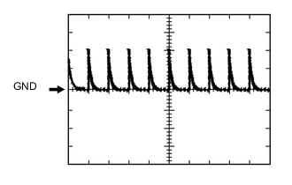
Waveform 3
Item Content Terminal No. (Symbol) D5-26 (RFOG)*2 - Body ground Tool setting 5 V/DIV., 60 ms./DIV. Condition Ignition switch ON
Rear fog light switch off
Item Content Terminal No. (Symbol) MB-18 (HF) - Body ground Tool setting 5 V/DIV., 60 ms./DIV. Condition Ignition switch ON
Dimmer switch not in high flash position
Item Content Terminal No. (Symbol) D5-23 (A)*1 - Body ground Tool setting 5 V/DIV., 60 ms./DIV. Condition Ignition switch ON
Light control switch not in AUTO position
-
-
*1: w/ Automatic Light Control System
-
*2: w/ Rear Fog Light
-
-
HEADLIGHT LEVELING ECU ASSEMBLY

Text in Illustration *1 Headlight Leveling ECU Assembly - -
-
Measure the voltage according to the value(s) in the table below.
Terminal No. Wiring Color Terminal Description Condition Specified Condition A16-13(R-DIAG) - Body ground V - Body ground Headlight drive output Always Below 1.5 V A16-15(L-DIAG) - Body ground V-W - Body ground Headlight drive output Always Below 1.5 V
-