POWER WINDOW CONTROL SYSTEM Front Passenger Side Power Window does not Operate with Front Passenger Side Power Window Switch
DESCRIPTION
When the ignition switch is ON, the power window regulator motor assembly (for front passenger side) is operated by the power window regulator switch assembly. The power window regulator motor assembly (for front passenger side) has motor, regulator and ECU functions.
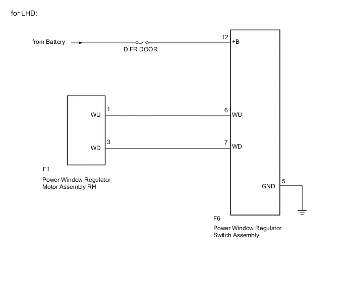
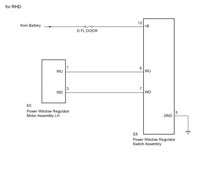
WIRING DIAGRAM
CAUTION / NOTICE / HINT
Note
-
When the power window regulator master switch assembly, power window regulator switch assembly and power window regulator motor assembly is reinstalled or replaced, the power window control system must be initialized Click here.
-
Inspect the fuses for circuits related to this system before performing the following inspection procedure.
PROCEDURE
-
PERFORM ACTIVE TEST USING GTS
-
Connect the GTS to the DLC3.
-
Turn the ignition switch to ON.
-
Turn the GTS on.
-
Enter the following menus: Body Electrical / Master Switch / Active Test.
-
Perform the Active Test according to the display on the GTS.
Master Switch Tester Display Test Part Control Range Diagnostic Note Power Window Front passenger side power window OFF / UP / DOWN - OK Front passenger side door power window operates normally. CAUTION:
Be careful to avoid injuries as this test causes vehicle parts to move. During the Active Test, the jam protection function will not operate.
Result Result Proceed to NG A OK B
B 
REPLACE POWER WINDOW REGULATOR SWITCH ASSEMBLY Click here
A 
-
-
CHECK HARNESS AND CONNECTOR (POWER WINDOW REGULATOR SWITCH - BATTERY)
-
Disconnect the F6*1 or E8*2 power window regulator switch assembly connector.
-
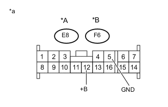
Text in Illustration *A for LHD *B for RHD *a Front view of wire harness connector
(to Front Power Window Regulator Switch Assembly)
Measure the voltage and resistance according to the value(s) in the table below.
Standard Voltage Tester Connection Condition Specified Condition F6-12 (+B)*1 - Body ground Always 11 to 14 V E8-12 (+B)*2 - Body ground Always 11 to 14 V Standard Resistance Tester Connection Condition Specified Condition F6-5 (GND)*1 - Body ground Always Below 1 Ω E8-5 (GND)*2 - Body ground Always Below 1 Ω
-
*1: for LHD
-
*2: for RHD
-
NG
REPAIR OR REPLACE HARNESS OR CONNECTOR
OK
-
-
CHECK HARNESS AND CONNECTOR (POWER WINDOW REGULATOR SWITCH - POWER WINDOW MOTOR)
-
Disconnect the F6*1 or E8*2 power window regulator switch assembly connector.
-
Disconnect the F1*1 or E5*2 power window regulator motor assembly connector.
-
Measure the resistance according to the value(s) in the table below.
Standard Resistance (Check for Open) Tester Connection Condition Specified Condition F6-6 (WU) - F1-1 (WU)*1 Always Below 1 Ω F6-7 (WD) - F1-3 (WD)*1 Always Below 1 Ω E8-6 (WU) - E5-1 (WU)*2 Always Below 1 Ω E8-7 (WD) - E5-3 (WD)*2 Always Below 1 Ω Standard Resistance (Check for Short) Tester Connection Condition Specified Condition F6-6 (WU)*1 - Body ground Always 10 kΩ or higher F6-7 (WD)*1 - Body ground Always 10 kΩ or higher E8-6 (WU)*2 - Body ground Always 10 kΩ or higher E8-7 (WD)*2 - Body ground Always 10 kΩ or higher
-
*1: for LHD
-
*2: for RHD
-
NG
REPAIR OR REPLACE HARNESS OR CONNECTOR
OK
-
-
REPLACE POWER WINDOW REGULATOR SWITCH ASSEMBLY
-
Temporarily replace the power window regulator switch assembly with a new or normally functioning one Click here.
-
Check the power window regulator switch assembly operates Click here.
OK Front passenger side door power window operates normally. Result Result Proceed to Operate A Does not operate B
A
END (POWER WINDOW REGULATOR SWITCH ASSEMBLY WAS DEFECTIVE)
B
REPLACE POWER WINDOW REGULATOR MOTOR ASSEMBLY Click here
-