POWER WINDOW CONTROL SYSTEM, Diagnostic DTC:B2313, B2316
| DTC Code | DTC Name |
|---|---|
| B2313 | Driver Side Glass Position Initialization Incomplete |
| B2316 | Passenger Side Glass Position Initialization Incomplete |
DESCRIPTION
The power window regulator motor assembly (driver side or front passenger side) is operated by the power window regulator master switch assembly or the power window regulator switch assembly. When the ECU (power window regulator master switch assembly) determines that the power window regulator master switch assembly or the power window regulator switch assembly has not been initialized, or the pulse output circuit of the power window regulator motor assembly (driver side or front passenger side) is abnormal, DTC B2313 or B2316 is stored.
| DTC No. | DTC Detection Condition | Trouble Area |
|---|---|---|
| B2313 |
|
|
| B2316 |
|
|
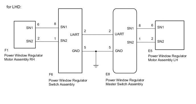
WIRING DIAGRAM
PROCEDURE
-
PERFORM INITIALIZATION
-
Turn the ignition switch to ON.
-
Initialize the power window regulator master switch assembly or power window regulator switch assembly Click here.
NEXT 
-
-
CHECK DTC OUTPUT
-
Clear the DTC Click here.
-
Check for DTCs Click here.
Tech Tips
Check for DTCs for the power window regulator motor assembly that has DTC B2313 or B2316 stored in its ECU.
OK DTC is not output. Result Result Proceed to No DTCs output A DTCs B2311 or B2314 is output B DTCs B2312 or B2315 is output B DTC B2313 is output C DTC B2316 is output D
A 
END (POWER WINDOW CONTROL SYSTEM HAS NOT BEEN INITIALIZED)
B
GO TO OTHER PROBLEM (Proceed to Problem Symptoms Table) Click here
D 
CHECK POWER WINDOW REGULATOR SWITCH ASSEMBLY Click here
C
-
-
CHECK POWER WINDOW REGULATOR MASTER SWITCH ASSEMBLY
-
Using an oscilloscope, check the waveform.
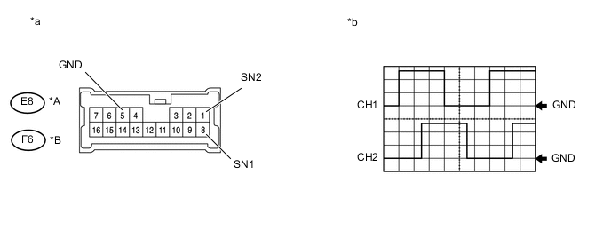
Text in Illustration *A for LHD *B for RHD *a Component with harness connected (Power Window Regulator Master Switch Assembly) *b Waveform OK Tester Connection Condition Tool Setting Specified Condition CH1: E8-8 (SN1) - E8-5 (GND)*1
CH2: E8-1 (SN2) - E8-5 (GND)*1
CH1: F6-8 (SN1) - F6-5 (GND)*2
CH2: F6-1 (SN2) - F6-5 (GND)*2
Ignition switch ON, power window regulator master switch assembly OFF → UP or DOWN 5 V/DIV., 2 ms./DIV. Pulse generation (See waveform)
-
*1: for LHD
-
*2: for RHD
Result Result Proceed to NG A OK B -
B
REPLACE POWER WINDOW REGULATOR MASTER SWITCH ASSEMBLY Click here
A
-
-
CHECK HARNESS AND CONNECTOR (POWER WINDOW REGULATOR MASTER SWITCH ASSEMBLY - POWER WINDOW REGULATOR MOTOR ASSEMBLY (FOR DRIVER SIDE))
-
Disconnect the E8*1 or F6*2 power window regulator master switch assembly connector.
-
Disconnect the E5*1 or F1*2 power window regulator motor assembly (for driver side) connector.
-
Measure the resistance according to the value(s) in the table below.
Standard Resistance (Check for Open) Tester Connection Condition Specified Condition E8-8 (SN1) - E5-6 (SN1)*1 Always Below 1 Ω E8-1 (SN2) - E5-2 (SN2)*1 Always Below 1 Ω F6-8 (SN1) - F1-6 (SN1)*2 Always Below 1 Ω F6-1 (SN2) - F1-2 (SN2)*2 Always Below 1 Ω Standard Resistance (Check for Short) Tester Connection Condition Specified Condition E8-8 (SN1) or E5-6 (SN1) - Body ground*1 Always 10 kΩ or higher E8-1 (SN2) or E5-2 (SN2) - Body ground*1 Always 10 kΩ or higher F6-8 (SN1) or F1-6 (SN1) - Body ground*2 Always 10 kΩ or higher F6-1 (SN2) or F1-2 (SN2) - Body ground*2 Always 10 kΩ or higher
-
*1: for LHD
-
*2: for RHD
-
OK
REPLACE POWER WINDOW REGULATOR MOTOR ASSEMBLY (for Driver Side) Click here
NG
REPAIR OR REPLACE HARNESS OR CONNECTOR
-
-
CHECK POWER WINDOW REGULATOR SWITCH ASSEMBLY
-
Using an oscilloscope, check the waveform.
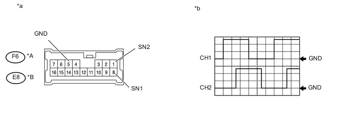
Text in Illustration *A for LHD *B for RHD *a Component with harness connected (Power Window Regulator Switch Assembly) *b Waveform OK Tester Connection Condition Tool Setting Specified Condition CH1: F6-8 (SN1) - F6-5 (GND)*1
CH2: F6-1 (SN2) - F6-5 (GND)*1
CH1: E8-8 (SN1) - E8-5 (GND)*2
CH2: E8-1 (SN2) - E8-5 (GND)*2
Ignition switch ON, power window regulator switch assembly OFF → UP or DOWN 5 V/DIV., 2 ms./DIV. Pulse generation (See waveform)
-
*1: for LHD
-
*2: for RHD
Result Result Proceed to NG A OK B -
B
REPLACE POWER WINDOW REGULATOR SWITCH ASSEMBLY Click here
A
-
-
CHECK HARNESS AND CONNECTOR (POWER WINDOW REGULATOR SWITCH - POWER WINDOW REGULATOR MOTOR (FOR FRONT PASSENGER SIDE))
-
Disconnect the F6*1 or E8*2 power window regulator switch assembly connector.
-
Disconnect the F1*1 or E5*2 power window regulator motor assembly (for passenger side) connector.
-
Measure the resistance according to the value(s) in the table below.
Standard Resistance (Check for Open) Tester Connection Condition Specified Condition F6-8 (SN1) - F1-6 (SN1)*1 Always Below 1 Ω F6-1 (SN2) - F1-2 (SN2)*1 Always Below 1 Ω E8-8 (SN1) - E5-6 (SN1)*2 Always Below 1 Ω E8-1 (SN2) - E5-2 (SN2)*2 Always Below 1 Ω Standard Resistance (Check for Short) Tester Connection Condition Specified Condition F6-8 (SN1) or F1-6 (SN1) - Body ground*1 Always 10 kΩ or higher F6-1 (SN2) or F1-2 (SN2) - Body ground*1 Always 10 kΩ or higher E8-8 (SN1) or E5-6 (SN1) - Body ground*2 Always 10 kΩ or higher E8-1 (SN2) or E5-2 (SN2) - Body ground*2 Always 10 kΩ or higher
-
*1: for LHD
-
*2: for RHD
-
OK
REPLACE POWER WINDOW REGULATOR MOTOR ASSEMBLY (for Front Passenger Side) Click here
NG
REPAIR OR REPLACE HARNESS OR CONNECTOR
-