POWER WINDOW CONTROL SYSTEM, Diagnostic DTC:B2312, B2315
| DTC Code | DTC Name |
|---|---|
| B2312 | Driver Side Master Switch ON Stuck |
| B2315 | Passenger Side P/W Switch ON Stuck |
DESCRIPTION
The power window regulator motor assembly is operated by the power window master switch assembly or power window regulator switch assembly. The power window regulator motor assembly has motor, regulator and ECU functions. These DTCs are output when the ECU built into the regulator motor and master switch determines that the power window master switch assembly or power window regulator switch assembly is stuck.
Note
-
When the power window regulator master switch assembly, power window regulator switch assembly and power window regulator motor assembly is reinstalled or replaced, the power window control system must be initialized Click here.
-
When the jam protection function malfunctions and prevents the door glass from closing completely, the following procedure can be used to cancel the jam protection function and allow the door glass to be closed*1.
-
Repeat the AUTO UP maintain → jam protection function operation twice in succession*2.
-
The third repeat of the AUTO UP maintain operation will cause the position of the upper edge of the door glass to be relearned, allowing the door glass to be closed.
-
*1: In some cases, the state of the door glass or regulator may prevent the glass from being closed, even in this mode.
-
*2: If any action other that the AUTO UP operation (DOWN operation, IG OFF, timer-operated OFF, index operation, etc.) is performed between the operation of the jam protection function and the AUTO UP maintain, this count will be reset.
| DTC No. | DTC Detection Condition | Trouble Area |
|---|---|---|
| B2312 |
|
Power window regulator master switch assembly |
| B2315 |
|
|
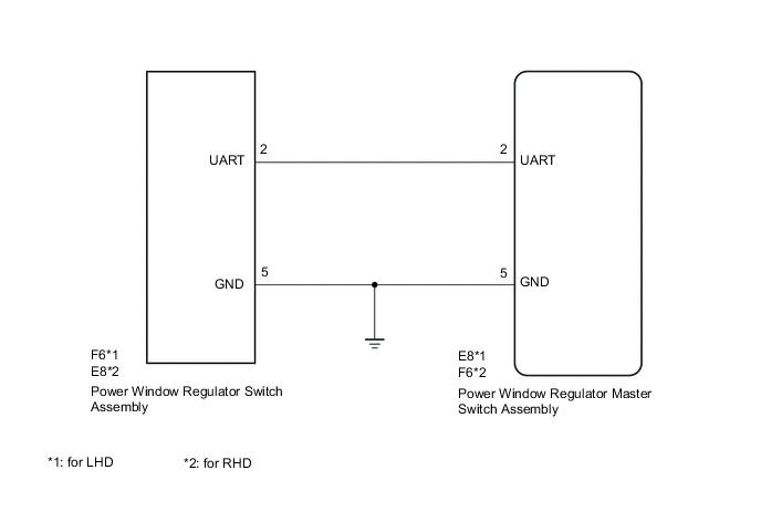
WIRING DIAGRAM
PROCEDURE
-
CHECK DTC OUTPUT
-
Clear the DTCs Click here.
-
Check the DTCs Click here.
Result Result Proceed to DTC B2312 is output A DTC B2315 is output B
A 
REPLACE POWER WINDOW REGULATOR MASTER SWITCH ASSEMBLY Click here
B 
-
-
READ VALUE USING GTS
-
Connect the GTS to the DLC3.
-
Turn the ignition switch to ON.
-
Turn the GTS on.
-
Enter the following menus: Body Electrical / Master Switch / Data List.
-
According to the display on the GTS, read the Data List.
Master Switch Tester Display Measurement Item/Range Normal Condition Diagnostic Note P Door P/W Auto SW Front passenger side power window auto switch signal / ON or OFF ON: Front passenger side power window auto up/down switch operated
OFF: Front passenger side power window switch not operated
- P Door P/W Up SW Front passenger side power window manual up signal / ON or OFF ON: Front passenger side power window manual up switch operated
OFF: Front passenger side power window switch not operated
- P Door P/W Down SW Front passenger side power window manual down signal / ON or OFF ON: Front passenger side power window manual down switch operated
OFF: Front passenger side power window switch not operated
- OK The GTS display changes normally when regulator switch is operated.
NG
REPLACE POWER WINDOW REGULATOR SWITCH ASSEMBLY Click here
OK
-
-
CHECK HARNESS AND CONNECTOR (POWER WINDOW MASTER SWITCH - POWER WINDOW MOTOR)
-
Disconnect the E8*1 or F6*2 power window regulator master switch assembly connector.
-
Disconnect the F6*1 or E8*2 power window regulator switch assembly connector.
-
Measure the resistance according to the value(s) in the table below.
Standard Resistance (Check for Open) Tester Connection Condition Specified Condition E8-2 (UART) - F6-2 (UART) Always Below 1 Ω Standard Resistance (Check for Short) Tester Connection Condition Specified Condition E8-2 (UART)*1 - Body ground Always 10 kΩ or higher F6-2 (UART)*2 - Body ground Always 10 kΩ or higher
-
*1: for LHD
-
*2: for RHD
-
OK
REPLACE POWER WINDOW REGULATOR MASTER SWITCH ASSEMBLY Click here
NG
REPAIR OR REPLACE HARNESS OR CONNECTOR
-