POWER WINDOW CONTROL SYSTEM, Diagnostic DTC:B2311, B2314
| DTC Code | DTC Name |
|---|---|
| B2311 | Driver Side Motor Malfunction |
| B2314 | Passenger Side Motor Malfunction |
DESCRIPTION
The power window regulator motor is operated by the power window regulator master switch assembly and power window regulator assembly. The power window regulator motor assembly (for driver side and front passenger side) has motor, regulator and ECU functions.
These DTCs are output when the power window regulator motor assembly (for driver side and front passenger side) has a malfunction, or the power window regulator master switch assembly and power window regulator switch assembly has a malfunction.
| DTC No. | DTC Detection Condition | Trouble Area |
|---|---|---|
| B2311 |
|
|
| B2314 |
|
|
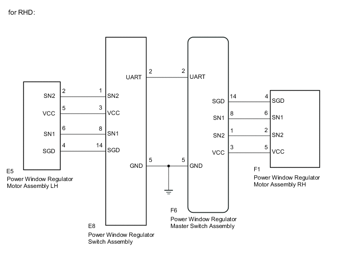
WIRING DIAGRAM

CAUTION / NOTICE / HINT
Note
-
When the power window regulator master switch assembly, power window regulator switch assembly and power window regulator motor assembly is reinstalled or replaced, the power window control system must be initialized Click here.
-
Inspect the fuses for circuits related to this system before performing the following inspection procedure.
PROCEDURE
-
CHECK DTC OUTPUT
-
Clear the DTC Click here.
-
Check for DTCs Click here.
Result Result Proceed to DTC B2311 is output A DTC B2314 is output B
B 
READ VALUE USING GTS Click here
A 
-
-
READ VALUE USING GTS
-
Connect the GTS to the DLC3.
-
Turn the ignition switch to ON.
-
Turn the GTS on.
-
Enter the following menus: Body Electrical / Master Switch / Data List.
-
According to the display on the GTS read the Data List.
Master Switch Tester Display Measurement Item/Range Normal Condition Diagnostic Note Current D Sensor Fail Mode1 Driver side sensor fail mode1(power of sensor malfunction) /Detected or Not Detected Not Detected - Current D Sensor Fail Mode2 Driver side sensor fail mode2(Pulse sensor1 malfunction) /Detected or Not Detected Not Detected - Current D Sensor Fail Mode3 Driver side sensor fail mode3(Pulse sensor2 malfunction) /Detected or Not Detected Not Detected - Current D Sensor Fail Mode4 Driver side sensor fail mode4(Pulse direction error) /Detected or Not Detected Not Detected - Current D Sensor Fail Mode5 Driver side sensor fail mode5(Pulse stop) /Detected or Not Detected Not Detected - Current D Sensor Fail Mode6 Driver side sensor fail mode6(Dead zone opening direction error) /Detected or Not Detected Not Detected - OK On the GTS screen, Not Detected is displayed. Result Result Proceed to NG A OK B
B 
REPLACE POWER WINDOW REGULATOR MASTER SWITCH ASSEMBLY Click here
A
-
-
CHECK HARNESS AND CONNECTOR (POWER WINDOW REGULATOR MASTER SWITCH - POWER WINDOW REGULATOR MOTOR)
-
Disconnect the E8*1 or F6*2 power window regulator master switch assembly connector.
-
Disconnect the E5*1 or F1*2 power window regulator motor assembly connector.
-
Measure the resistance according to the value(s) in the table below.
Standard Resistance (Check for Open) Current D Sensor Fail Mode 1 Tester connection Condition Specified condition E8-3 (VCC) - E5-5 (VCC)*1 Always Below 1 Ω E8-14 (SGD) - E5-4 (SGD)*1 Always Below 1 Ω F6-3 (VCC) - F1-5 (VCC)*2 Always Below 1 Ω F6-14 (SGD) - F1-4 (SGD)*2 Always Below 1 Ω Current D Sensor Fail Mode 2 Tester connection Condition Specified condition E8-8 (SN1) - E5-6 (SN1)*1 Always Below 1 Ω F6-8 (SN1) - F1-6 (SN1)*2 Always Below 1 Ω Current D Sensor Fail Mode 3 Tester connection Condition Specified condition E8-1 (SN2) - E5-2 (SN2)*1 Always Below 1 Ω F6-1 (SN2) - F1-2 (SN2)*2 Always Below 1 Ω Current D Sensor Fail Mode 4 Tester connection Condition Specified condition E8-1 (SN2) - E5-2 (SN2)*1 Always Below 1 Ω E8-8 (SN1) - E5-6 (SN1)*1 Always Below 1 Ω F6-1 (SN2) - F1-2 (SN2)*2 Always Below 1 Ω F6-8 (SN1) - F1-6 (SN1)*2 Always Below 1 Ω Current D Sensor Fail Mode 5 Tester connection Condition Specified condition E8-1 (SN2) - E5-2 (SN2)*1 Always Below 1 Ω E8-3 (VCC) - E5-5 (VCC)*1 Always Below 1 Ω E8-8 (SN1) - E5-6 (SN1)*1 Always Below 1 Ω E8-14 (SGD) - E5-4 (SGD)*1 Always Below 1 Ω F6-1 (SN2) - F1-2 (SN2)*2 Always Below 1 Ω F6-3 (VCC) - F1-5 (VCC)*2 Always Below 1 Ω F6-8 (SN1) - F1-6 (SN1)*2 Always Below 1 Ω F6-14 (SGD) - F1-4 (SGD)*2 Always Below 1 Ω Current D Sensor Fail Mode 6 Tester connection Condition Specified condition E8-1 (SN2) - E5-2 (SN2)*1 Always Below 1 Ω E8-3 (VCC) - E5-5 (VCC)*1 Always Below 1 Ω E8-8 (SN1) - E5-6 (SN1)*1 Always Below 1 Ω E8-14 (SGD) - E5-4 (SGD)*1 Always Below 1 Ω F6-1 (SN2) - F1-2 (SN2)*2 Always Below 1 Ω F6-3 (VCC) - F1-5 (VCC)*2 Always Below 1 Ω F6-8 (SN1) - F1-6 (SN1)*2 Always Below 1 Ω F6-14 (SGD) - F1-4 (SGD)*2 Always Below 1 Ω Standard Resistance (Check for Short) Current D Sensor Fail Mode 1 Tester connection Condition Specified condition E8-3 (VCC)*1 Body ground Always 10 kΩ or higher E8-14 (SGD)*1 Body ground Always 10 kΩ or higher F6-3 (VCC)*2 Body ground Always 10 kΩ or higher F6-14 (SGD)*2 Body ground Always 10 kΩ or higher Current D Sensor Fail Mode 2 Tester connection Condition Specified condition E8-8 (SN1)*1 -Body ground Always 10 kΩ or higher F6-8 (SN1)*2 -Body ground Always 10 kΩ or higher Current D Sensor Fail Mode 3 Tester connection Condition Specified condition E8-1 (SN2)*1 - Body ground Always 10 kΩ or higher F6-1 (SN2)*2 - Body ground Always 10 kΩ or higher Current D Sensor Fail Mode 4 Tester connection Condition Specified condition E8-1 (SN2)*1- Body ground Always 10 kΩ or higher E8-8 (SN1)*1 - Body ground Always 10 kΩ or higher F6-1 (SN2)*2- Body ground Always 10 kΩ or higher F6-8 (SN1)*2 - Body ground Always 10 kΩ or higher Current D Sensor Fail Mode 5 Tester connection Condition Specified condition E8-1 (SN2)*1- Body ground Always 10 kΩ or higher E8-3 (VCC)*1 - Body ground Always 10 kΩ or higher E8-8 (SN1)*1 - Body ground Always 10 kΩ or higher E8-14 (SGD)*1 - Body ground Always 10 kΩ or higher F6-1 (SN2)*2- Body ground Always 10 kΩ or higher F6-3 (VCC)*2 - Body ground Always 10 kΩ or higher F6-8 (SN1)*2 - Body ground Always 10 kΩ or higher F6-14 (SGD)*2 - Body ground Always 10 kΩ or higher Current D Sensor Fail Mode 6 Tester connection Condition Specified condition E8-3 (VCC)*1 - Body ground Always 10 kΩ or higher E8-8 (SN1)*1 - Body ground Always 10 kΩ or higher E8-14 (SGD)*1 - Body ground Always 10 kΩ or higher E8-14 (SGD)*1 - Body ground Always 10 kΩ or higher F6-3 (VCC)*2 - Body ground Always 10 kΩ or higher F6-8 (SN1)*2 - Body ground Always 10 kΩ or higher F6-14 (SGD)*2 - Body ground Always 10 kΩ or higher F6-14 (SGD)*2 - Body ground Always 10 kΩ or higher
-
*1: for LHD
-
*2: for RHD
-
NG
REPAIR OR REPLACE HARNESS OR CONNECTOR
OK
-
-
INSPECT POWER WINDOW REGULATOR MOTOR ASSEMBLY
-
Remove the power window regulator motor assembly Click here.
-
Inspect the power window regulator motor assembly Click here.
NG
REPLACE POWER WINDOW REGULATOR MOTOR ASSEMBLY Click here
OK
-
-
REPLACE POWER WINDOW REGULATOR MASTER SWITCH ASSEMBLY
-
Temporarily replace the power window regulator master switch assembly with a new or normally functioning one Click here.
-
Check the power window regulator master switch assembly operates Click here.
OK Driver side door power window operates normally. Result Result Proceed to Does not operate A Operate B
A
REPLACE POWER WINDOW REGULATOR ASSEMBLY
B
END
-
-
READ VALUE USING GTS
-
Connect the GTS to the DLC3.
-
Turn the ignition switch to ON.
-
Turn the GTS on.
-
Enter the following menus: Body Electrical / Master Switch / Data List.
-
According to the display on the GTS read the Data List.
Master Switch Tester Display Measurement Item/Range Normal Condition Diagnostic Note Current P Sensor Fail Mode1 Front passenger side sensor fail mode1(power of sensor malfunction) /Detected or Not Detected Not Detected - Current P Sensor Fail Mode2 Front passenger side sensor fail mode2(Pulse sensor1 malfunction) /Detected or Not Detected Not Detected - Current P Sensor Fail Mode3 Front passenger side sensor fail mode3(Pulse sensor2 malfunction) /Detected or Not Detected Not Detected - Current P Sensor Fail Mode4 Front passenger side sensor fail mode4(Pulse direction error) /Detected or Not Detected Not Detected - Current P Sensor Fail Mode5 Front passenger side sensor fail mode5(Pulse stop) /Detected or Not Detected Not Detected - Current P Sensor Fail Mode6 Front passenger side sensor fail mode6(Dead zone opening direction error) /Detected or Not Detected Not Detected - OK On the GTS screen, Not Detected is displayed. Result Result Proceed to NG A OK B
B
REPLACE POWER WINDOW REGULATOR MASTER SWITCH ASSEMBLY Click here
A
-
-
CHECK HARNESS AND CONNECTOR (POWER WINDOW REGULATOR SWITCH - POWER WINDOW REGULATOR MOTOR)
-
Disconnect the F6*1 or E8*2 power window regulator master switch assembly connector.
-
Disconnect the F1*1 or E5*2 power window regulator motor assembly connector.
-
Measure the resistance according to the value(s) in the table below.
Standard Resistance (Check for Open) Current P Sensor Fail Mode 1 Tester connection Condition Specified condition F6-3 (VCC) - F1-5 (VCC)*1 Always Below 1 Ω F6-14 (SGD) - F1-4 (SGD)*1 Always Below 1 Ω E8-3 (VCC) - E5-5 (VCC)*2 Always Below 1 Ω E8-14 (SGD) - E5-4 (SGD)*2 Always Below 1 Ω Current P Sensor Fail Mode 2 Tester connection Condition Specified condition F6-8 (SN1) - F1-6 (SN1)*1 Always Below 1 Ω E8-8 (SN1) - E5-6 (SN1)*2 Always Below 1 Ω Current P Sensor Fail Mode 3 Tester connection Condition Specified condition F6-1 (SN2) - F1-2 (SN2)*1 Always Below 1 Ω E8-1 (SN2) - E5-2 (SN2)*2 Always Below 1 Ω Current P Sensor Fail Mode 4 Tester connection Condition Specified condition F6-1 (SN2) - F1-2 (SN2)*1 Always Below 1 Ω F6-8 (SN1) - F1-6 (SN1)*1 Always Below 1 Ω E8-1 (SN2) - E5-2 (SN2)*2 Always Below 1 Ω E8-8 (SN1) - E5-6 (SN1)*2 Always Below 1 Ω Current P Sensor Fail Mode 5 Tester connection Condition Specified condition F6-1 (SN2) - F1-2 (SN2)*1 Always Below 1 Ω F6-3 (VCC) - F1-5 (VCC)*1 Always Below 1 Ω F6-8 (SN1) - F1-6 (SN1)*1 Always Below 1 Ω F6-14 (SGD) - F1-4 (SGD)*1 Always Below 1 Ω E8-1 (SN2) - E5-2 (SN2)*2 Always Below 1 Ω E8-3 (VCC) - E5-5 (VCC)*2 Always Below 1 Ω E8-8 (SN1) - E5-6 (SN1)*2 Always Below 1 Ω E8-14 (SGD) - E5-4 (SGD)*2 Always Below 1 Ω Current P Sensor Fail Mode 6 Tester connection Condition Specified condition F6-1 (SN2) - F1-2 (SN2)*1 Always Below 1 Ω F6-3 (VCC) - F1-5 (VCC)*1 Always Below 1 Ω F6-8 (SN1) - F1-6 (SN1)*1 Always Below 1 Ω F6-14 (SGD) - F1-4 (SGD)*1 Always Below 1 Ω E8-1 (SN2) - E5-2 (SN2)*2 Always Below 1 Ω E8-3 (VCC) - E5-5 (VCC)*2 Always Below 1 Ω E8-8 (SN1) - E5-6 (SN1)*2 Always Below 1 Ω E8-14 (SGD) - E5-4 (SGD)*2 Always Below 1 Ω Standard Resistance (Check for Short) Current P Sensor Fail Mode 1 Tester connection Condition Specified condition F6-3 (VCC)*1 - Body ground Always 10 kΩ or higher F6-14 (SGD)*1 - Body ground Always 10 kΩ or higher E8-3 (VCC)*2 - Body ground Always 10 kΩ or higher E8-14 (SGD)*2 - Body ground Always 10 kΩ or higher Current P Sensor Fail Mode 2 Tester connection Condition Specified condition F6-8 (SN1)*1 - Body ground Always 10 kΩ or higher E8-8 (SN1)*2 - Body ground Always 10 kΩ or higher Current P Sensor Fail Mode 3 Tester connection Condition Specified condition F6-1 (SN2)*1 - Body ground Always 10 kΩ or higher E8-1 (SN2)*2 - Body ground Always 10 kΩ or higher Current P Sensor Fail Mode 4 Tester connection Condition Specified condition F6-1 (SN2)*1 - Body ground Always 10 kΩ or higher F6-8 (SN1)*1 - Body ground Always 10 kΩ or higher E8-1 (SN2)*2 - Body ground Always 10 kΩ or higher E8-8 (SN1)*2 - Body ground Always 10 kΩ or higher Current P Sensor Fail Mode 5 Tester connection Condition Specified condition F6-1 (SN2)*1 - Body ground Always 10 kΩ or higher F6-3 (VCC)*1 - Body ground Always 10 kΩ or higher F6-8 (SN1)*1 - Body ground Always 10 kΩ or higher F6-14 (SGD)*1 - Body ground Always 10 kΩ or higher E8-1 (SN2)*2 - Body ground Always 10 kΩ or higher E8-3 (VCC)*2 - Body ground Always 10 kΩ or higher E8-8 (SN1)*2 - Body ground Always 10 kΩ or higher E8-14 (SGD)*2 - Body ground Always 10 kΩ or higher Current P Sensor Fail Mode 6 Tester connection Condition Specified condition F6-1 (SN2)*1 - Body ground Always 10 kΩ or higher F6-3 (VCC)*1 - Body ground Always 10 kΩ or higher F6-8 (SN1)*1 - Body ground Always 10 kΩ or higher F6-14 (SGD)*1 - Body ground Always 10 kΩ or higher E8-1 (SN2)*2 - Body ground Always 10 kΩ or higher E8-3 (VCC)*2 - Body ground Always 10 kΩ or higher E8-8 (SN1)*2 - Body ground Always 10 kΩ or higher E8-14 (SGD)*2 - Body ground Always 10 kΩ or higher
-
*1: for LHD
-
*2: for RHD
-
NG
REPAIR OR REPLACE HARNESS OR CONNECTOR
OK
-
-
INSPECT POWER WINDOW REGULATOR MOTOR ASSEMBLY
-
Remove the power window regulator motor assembly Click here.
-
Inspect the power window regulator motor assembly Click here.
NG
REPLACE POWER WINDOW REGULATOR MOTOR ASSEMBLY Click here
OK
-
-
REPLACE POWER WINDOW REGULATOR SWITCH ASSEMBLY
-
Temporarily replace the power window regulator switch assembly with a new or normally functioning one Click here.
-
Check the power window regulator switch assembly operates Click here.
OK Front passenger side door power window operates normally. Result Result Proceed to Does not operate A Operate B
B
END
A
-
-
REPLACE POWER WINDOW REGULATOR MASTER SWITCH ASSEMBLY
-
Temporarily replace the power window regulator master switch assembly with a new or normally functioning one Click here.
-
Check the power window regulator master switch assembly operates Click here.
OK Driver side door power window operates normally. Result Result Proceed to Does not operate A Operate B
A
REPLACE POWER WINDOW REGULATOR ASSEMBLY
B
END
-