WINDOW DEFOGGER SYSTEM Rear Window Defogger System does not Operate
DESCRIPTION
When the ignition switch is ON, operating the rear window defogger switch activates the rear window defogger.
-
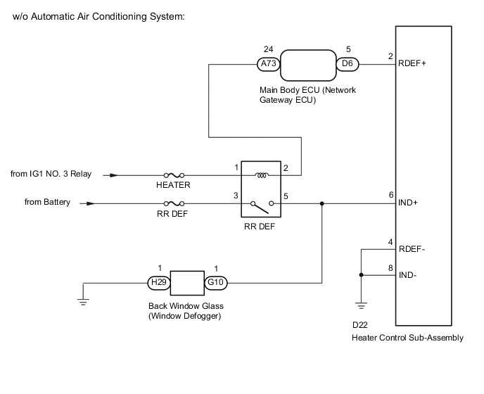
w/o Automatic Air Conditioning System:
-
The rear window defogger control is performed by the main body ECU (network gateway computer). When the main body ECU (network gateway computer) receives an on signal from the rear window defogger switch, it operates the RR DEF relay for 15 minutes. Also, when the main body ECU (network gateway computer) receives an off signal from the rear window defogger switch within 15 minutes, it stops operation of the RR DEF relay.
-
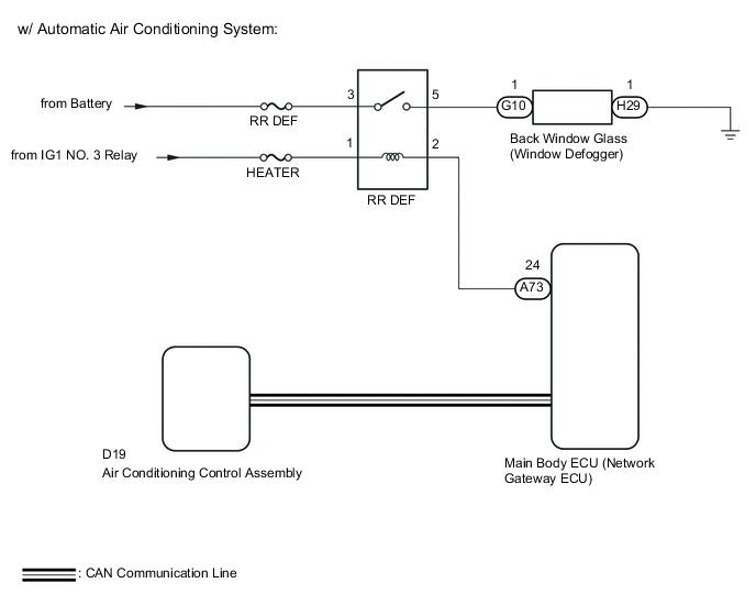
w/ Automatic Air Conditioning System:
-
The rear window defogger control is performed by the main body ECU (network gateway computer). When the rear window defogger switch is turned on, a rear window defogger activation request signal from the air conditioner control assembly is sent to the main body ECU (network gateway computer) via the CAN communication line, and the main body ECU (network gateway computer) operates the RR DEF relay for 15 minutes. Also, when the main body ECU (network gateway computer) receives a rear window defogger off signal within 15 minutes, it stops operation of the RR DEF relay.
WIRING DIAGRAM
CAUTION / NOTICE / HINT
Note
-
Perform the communication function inspections in How to Proceed with Troubleshooting to confirm that there are no CAN communication malfunctions before performing the following inspection Click here.
-
Inspect the fuses for circuits related to this system before performing the following inspection procedure.
PROCEDURE
-
PERFORM ACTIVE TEST USING GTS (RR DEF RELAY)
-
Connect the GTS to the DLC3.
-
Turn the ignition switch to ON.
-
Turn the GTS on.
-
Enter the following menus: Body / Main Body / Active Test.
-
According to the display on the GTS, perform the Active Test.
Main Body Tester Display Test Part Control Range Diagnostic Note Rear Defogger RR DEF relay OFF or ON - OK The window defogger system operates normally. Result Result Proceed to NG A OK B
B 
PROCEED TO NEXT CIRCUIT INSPECTION SHOWN IN PROBLEM SYMPTOMS TABLE
A 
-
-
INSPECT RR DEF RELAY
-
Remove the RR DEF relay from the engine room relay block.
-
Inspect the RR DEF relay Click here.
NG
REPLACE RELAY (RR DEF)
OK
-
-
CHECK HARNESS AND CONNECTOR (RR DEF RELAY - BATTERY)
-
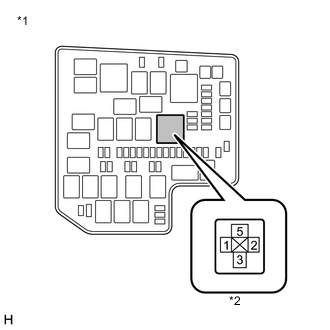
Text in Illustration *1 Engine Room Relay Block *2 RR DEF Relay Remove the RR DEF relay from the engine room relay block assembly.
-
Measure the voltage according to the value(s) in the table below.
Standard Voltage Tester Connection Switch Condition Specified Condition 1 - Body ground Ignition switch ON 11 to 14 V 3 - Body ground Always 11 to 14 V
NG
REPAIR OR REPLACE HARNESS OR CONNECTOR
OK
-
-
CHECK HARNESS AND CONNECTOR (RR DEF RELAY - MAIN BODY ECU (NETWORK GATEWAY ECU))
-
Remove the RR DEF relay from the engine room relay block assembly.
-
Disconnect the A73 main body ECU (network gateway ECU) connector.
-
Measure the resistance according to the value(s) in the table below.
Standard Resistance (Check for Open) Tester Connection Condition Specified Condition 2 - A73-24 Always Below 1 Ω Standard Resistance (Check for Short) Tester Connection Condition Specified Condition 2 - Body ground Always 10 kΩ higher Result Result Proceed to NG A OK (w/o Automatic Air Conditioning System) B OK (w/ Automatic Air Conditioning System) C
A
REPAIR OR REPLACE HARNESS OR CONNECTOR
C 
CHECK HARNESS AND CONNECTOR (BACK WINDOW GLASS (REAR WINDOW DEFOGGER) - RR DEF RELAY) Click here
B
-
-
CHECK HARNESS AND CONNECTOR (MAIN BODY ECU (NETWORK GATEWAY ECU) - HEATER CONTROL SUB-ASSEMBLY)
-
Disconnect the D6 main body ECU (network gateway ECU) connector.
-
Disconnect the D22 heater control sub-assembly connector.
-
Measure the resistance according to the value(s) in the table below.
Standard Resistance (Check for Open) Tester Connection Condition Specified Condition D6-5 - D22-2 (RDEF+) Always Below 1 Ω Standard Resistance (Check for Short) Tester Connection Condition Specified Condition D6-5 - Body ground Always 10 kΩ or higher
NG
REPAIR OR REPLACE HARNESS OR CONNECTOR
OK
-
-
INSPECT HEATER CONTROL SUB-ASSEMBLY
-
Remove the heater control sub-assembly Click here.
-
Inspect the heater control sub-assembly Click here.
NG
REPLACE HEATER CONTROL SUB-ASSEMBLY Click here
OK
-
-
CHECK HARNESS AND CONNECTOR (BACK WINDOW GLASS (REAR WINDOW DEFOGGER) - RR DEF RELAY)
-
Disconnect the G10 and H29 rear window defogger connector.
-
Remove the RR DEF relay from the engine room relay block assembly.
-
Measure the resistance according to the value(s) in the table below.
Standard Resistance (Check for Open) Tester Connection Switch Condition Specified Condition G10-1 - 5 Always Below 1 Ω Standard Resistance (Check for Short) Tester Connection Switch Condition Specified Condition H29-1 - Body ground Always Below 1 Ω G10-1 - Body ground Always 10 kΩ or higher
OK
REPAIR OR REPLACE BACK WINDOW GLASS (REAR WINDOW DEFOGGER) Click here
NG
REPAIR OR REPLACE HARNESS OR CONNECTOR
-