POWER WINDOW CONTROL SYSTEM TERMINALS OF ECU
-
POWER WINDOW REGULATOR MASTER SWITCH ASSEMBLY
-
Disconnect the E8*1 or F6*2 power window regulator master switch assembly connector.
-
*1: for LHD
-
*2: for RHD
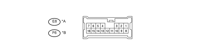
Text in Illustration *A for LHD *B for RHD -
-
Measure the voltage and resistance according to the value(s) in the table below.
Tech Tips
Measure the values on the wire harness side with the connector disconnected.
for LHD Tester Connection Wiring Color Terminal Description Condition Specified Condition E8-12 (+B) - E8 - 5 (GND) SB - B Power supply Always 11 to 14 V E8-5 (GND) - Body ground B - Body ground Ground Always Below 1 Ω for RHD Tester Connection Wiring Color Terminal Description Condition Specified Condition F6-12 (+B) - F6-5 (GND) SB - B Power supply Always 11 to 14 V F6-5 (GND) - Body ground B - Body ground Ground Always Below 1 Ω If the result is not as specified, there may be a malfunction in the wire harness.
-
Reconnect the E8*1 or F6*2 power window regulator master switch assembly connector.
-
*1: for LHD
-
*2: for RHD
-
-
Measure the voltage according to the value(s) in the table below.
for LHD Tester Connection Wiring Color Terminal Description Condition Specified Condition E8-6 (WU) - E8-5 (GND) W-B - B Power window motor UP output Ignition switch ON, power window regulator master switch OFF 11 to 14 V Ignition switch ON, power window regulator master switch UP (Manual operation) Below 1 V E8-6 (WU) - E8-5 (GND) W-B - B Power window motor AUTO UP output Ignition switch ON, driver side door power window fully open 11 to 14 V Ignition switch ON, driver side door power window moving, power window regulator master switch assembly fully pulled UP (Automatic operation) Below 1 V Ignition switch ON, driver side door power window fully closed 11 to 14 V E8-7 (WD) - E8-5 (GND) LG - B Power window motor DOWN output Ignition switch ON, power window regulator master switch OFF 11 to 14 V Ignition switch ON, power window regulator master switch DOWN (Manual operation) Below 1 V E8-7 (WD) - E8-5 (GND) LG - B Power window motor AUTO DOWN output Ignition switch ON, driver side door power window fully open 11 to 14 V Ignition switch ON, driver side door power window moving, power window regulator master switch assembly fully pushed DOWN (Automatic operation) Below 1 V Ignition switch ON, driver side door power window fully closed 11 to 14 V E8-8 (SN1) - E8-5 (GND) Y - B Hall IC in front power window regulator motor assembly LH input Ignition switch ON, power window regulator master switch assembly OFF → UP or DOWN Pulse generation (See waveform 1) E8-1 (SN2) - E8-5 (GND) GR - B Hall IC in front power window regulator motor assembly LH input Ignition switch ON, power window regulator master switch assembly OFF → UP or DOWN Pulse generation (See waveform 1) for RHD Tester Connection Wiring Color Terminal Description Condition Specified Condition F6-6 (WU) - F6-5 (GND) W-B - B Power window motor UP output Ignition switch ON, power window regulator master switch OFF 11 to 14 V Ignition switch ON, power window regulator master switch UP (Manual operation) Below 1 V F6-6 (WU) - F6-5 (GND) W-B - B Power window motor AUTO UP output Ignition switch ON, driver side door power window fully open 11 to 14 V Ignition switch ON, driver side door power window moving, power window regulator master switch assembly fully pulled UP (Automatic operation) Below 1 V Ignition switch ON, driver side door power window fully closed 11 to 14 V F6-7 (WD) - F6-5 (GND) LG - B Power window motor DOWN output Ignition switch ON, power window regulator master switch OFF 11 to 14 V Ignition switch ON, power window regulator master switch DOWN (Manual operation) Below 1 V F6-7 (WD) - F6-5 (GND) LG - B Power window motor AUTO DOWN output Ignition switch ON, driver side door power window fully open 11 to 14 V Ignition switch ON, driver side door power window moving, power window regulator master switch assembly fully pushed DOWN (Automatic operation) Below 1 V Ignition switch ON, driver side door power window fully closed 11 to 14 V F6-8 (SN1) - F6-5 (GND) Y - B Hall IC in front power window regulator motor assembly RH input Ignition switch ON, power window regulator master switch assembly OFF → UP or DOWN Pulse generation (See waveform 1) F6-1 (SN2) - F6-5 (GND) GR - B Hall IC in front power window regulator motor assembly RH input Ignition switch ON, power window regulator master switch assembly OFF → UP or DOWN Pulse generation (See waveform 1) -
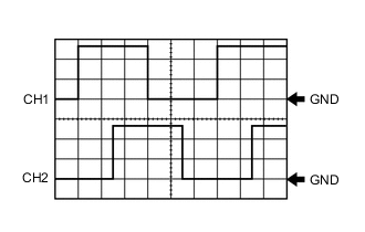
waveform 1
Measurement Condition Item Content Tester Connection CH1: E8-8 (SN1) - E8-5 (GND)*1
CH2: E8-1 (SN2) - E8-5 (GND)*1
CH1: F6-8 (SN1) - F6-5 (GND)*2
CH2 :F6-1 (SN2) - F6-5 (GND)*2
Tool Setting 5 V/DIV., 2 ms./DIV. Condition Ignition switch ON, power window regulator master switch assembly OFF → UP or DOWN
-
*1: for LHD
-
*2: for RHD
-
-
-
CHECK POWER WINDOW REGULATOR SWITCH ASSEMBLY
-
Disconnect the F6*1 or E8*2 power window regulator switch assembly connector.
-
*1: for LHD
-
*2: for RHD

Text in Illustration *A for LHD *B for RHD -
-
Measure the voltage according to the value(s) in the table below.
Tech Tips
Measure the values on the wire harness side with the connector disconnected.
for LHD Tester Connection Wiring Color Terminal Description Condition Specified Condition F6-12 (+B) - F6-5 (GND) SB - B Power supply Always 11 to 14 V F6-5 (GND) - Body ground B - Body ground Ground Always Bellow 1 V for RHD Tester Connection Wiring Color Terminal Description Condition Specified Condition E8-12 (+B) - E8-5 (GND) SB - B Power supply Always 11 to 14 V E8-5 (GND) - Body ground B - Body ground Ground Always Bellow 1 V If the result is not as specified, there may be a malfunction in the wire harness.
-
Reconnect the F6*1 or E8*2 power window regulator switch assembly connector.
-
*1: for LHD
-
*2: for RHD
-
-
Measure the voltage according to the value(s) in the table below.
for LHD Tester Connection Wiring Color Terminal Description Condition Specified Condition F6-6 (WU) - F6-5 (GND) W-B - B Power window motor UP output Ignition switch ON, power window regulator switch off 11 to 14 V Ignition switch ON, power window regulator switch UP (Manual operation) Bellow 1 V F6-6 (WU) - F6-5 (GND) W-B - B Power window motor AUTO UP output Ignition switch ON, front passenger side door power window fully open 11 to 14 V Ignition switch ON, front passenger side door power window moving, power window regulator switch assembly fully pulled UP (Automatic operation) Bellow 1 V Ignition switch ON, front passenger side door power window fully closed 11 to 14 V F6-7 (WD) - F6-5 (GND) LG - B Power window motor DOWN output Ignition switch ON, power window regulator switch off 11 to 14 V Ignition switch ON, power window regulator switch DOWN (Manual operation) Bellow 1 V F6-7 (WD) - F6-5 (GND) LG - B Power window motor AUTO DOWN output Ignition switch ON, front passenger side door power window fully open 11 to 14 V Ignition switch ON, front passenger side door power window moving, power window regulator switch assembly fully pulled DOWN (Automatic operation) Bellow 1 V Ignition switch ON, front passenger side door power window fully closed 11 to 14 V F6-8 (SN1) - F6-5 (GND) Y - B Hall IC in front power window regulator motor assembly RH input Ignition switch ON, power window regulator switch assembly OFF → UP or DOWN Pulse generation (See waveform 1) F6-1 (SN2) - F6-5 (GND) GR - B Hall IC in front power window regulator motor assembly RH input Ignition switch ON, power window regulator switch assembly OFF → UP or DOWN Pulse generation (See waveform 1) for RHD Tester Connection Wiring Color Terminal Description Condition Specified Condition E8-6 (WU) - E8-5 (GND) W-B - B Power window motor UP output Ignition switch ON, power window regulator switch off 11 to 14 V Ignition switch ON, power window regulator switch UP (Manual operation) Bellow 1 V E8-6 (WU) - E8-5 (GND) W-B - B Power window motor AUTO UP output Ignition switch ON, front passenger side door power window fully open 11 to 14 V Ignition switch ON, front passenger side door power window moving, power window regulator switch assembly fully pulled UP (Automatic operation) Bellow 1 V Ignition switch ON, front passenger side door power window fully closed 11 to 14 V E8-7 (WD) - E8-5 (GND) LG - B Power window motor DOWN output Ignition switch ON, power window regulator switch off 11 to 14 V Ignition switch ON, power window regulator switch DOWN (Manual operation) Bellow 1 V E8-7 (WD) - E8-5 (GND) LG - B Power window motor AUTO DOWN output Ignition switch ON, front passenger side door power window fully open 11 to 14 V Ignition switch ON, front passenger side door power window moving, power window regulator switch assembly fully pulled DOWN (Automatic operation) Bellow 1 V Ignition switch ON, front passenger side door power window fully closed 11 to 14 V E8-8 (SN1) - E8-5 (GND) Y - B Hall IC in front power window regulator motor assembly LH input Ignition switch ON, power window regulator switch assembly OFF → UP or DOWN Pulse generation (See waveform 1) E8-1 (SN2) - E8-5 (GND) GR - B Hall IC in front power window regulator motor assembly LH input Ignition switch ON, power window regulator switch assembly OFF → UP or DOWN Pulse generation (See waveform 1) -
waveform 1
Item Content Tester Connection CH1: F6-8 (SN1) - F6-5 (GND)*1
CH2: F6-1 (SN2) - F6-5 (GND)*1
CH1: E8-8 (SN1) - E8-5 (GND)*2
CH2: E8-1 (SN2) - E8-5 (GND)*2
Tool Setting 5 V/DIV., 2 ms./DIV. Condition Ignition switch ON, power window regulator switch assembly OFF → UP or DOWN
-
*1: for LHD
-
*2: for RHD
-
-
-
CHECK POWER WINDOW REGULATOR MOTOR ASSEMBLY
-
Disconnect the E5*1 or F1*2 power window regulator motor assembly (for driver side) connector.
-
*1: for LHD
-
*2: for RHD

Text in Illustration *A for LHD *B for RHD -
-
Measure the voltage and resistance according to the value(s) in the table below.
Tech Tips
Measure the values on the wire harness side with the connector disconnected.
for LHD Tester Connection Wiring Color Terminal Description Condition Specified Condition E5-5 (VCC) - E5-4 (SGD) W - R Power supply Always 11 to 14 V E5-4 (SGD) - Body ground R - Body ground Ground Always Below 1 Ω for RHD Tester Connection Wiring Color Terminal Description Condition Specified Condition F1-5 (VCC) - F1-4 (SGD) W - R Power supply Always 11 to 14 V F1-4 (SGD) - Body ground R - Body ground Ground Always Below 1 Ω If the result is not as specified, there may be a malfunction in the wire harness.
-
Reconnect the E5*1 or F1*2 power window regulator motor assembly (for driver side) connector.
-
*1: for LHD
-
*2: for RHD
-
-
Measure the voltage according to the value(s) in the table below.
for LHD Tester Connection Wiring Color Terminal Description Condition Specified Condition E5-1 (WU) - E5-4 (SGD) W-B - R Power window motor UP input Ignition switch ON, power window regulator master switch off 11 to 14 V Ignition switch ON, power window regulator master switch UP (Manual operation) Below 1 V E5-1 (WU) - E5-4 (SGD) W-B - R Power window motor AUTO UP input Ignition switch ON, driver side door power window fully open 11 to 14 V Ignition switch ON, driver side door power window moving, power window regulator master switch assembly fully pulled UP (Automatic operation) Below 1 V Ignition switch ON, driver side door power window fully closed 11 to 14 V E5-3 (WD) - E5-4 (SGD) LG - R Power window motor DOWN input Ignition switch ON, power window regulator master switch OFF 11 to 14 V Ignition switch ON, power window regulator master switch DOWN (Manual operation) Below 1 V E5-3 (WD) - E5-4 (SGD) LG - R Power window motor AUTO UP input Ignition switch ON, driver side door power window fully open 11 to 14 V Ignition switch ON, driver side door power window moving, power window regulator master switch assembly fully pulled DOWN (Automatic operation) Below 1 V Ignition switch ON, driver side door power window fully closed 11 to 14 V for RHD Tester Connection Wiring Color Terminal Description Condition Specified Condition F1-1 (WU) - F1-4 (SGD) W-B - R Power window motor UP input Ignition switch ON, power window regulator master switch off 11 to 14 V Ignition switch ON, power window regulator master switch UP (Manual operation) Below 1 V F1-1 (WU) - F1-4 (SGD) W-B - R Power window motor AUTO UP input Ignition switch ON, driver side door power window fully open 11 to 14 V Ignition switch ON, driver side door power window moving, power window regulator master switch assembly fully pulled UP (Automatic operation) Below 1 V Ignition switch ON, driver side door power window fully closed 11 to 14 V F1-3 (WD) - F1-4 (SGD) LG - R Power window motor DOWN input Ignition switch ON, power window regulator master switch OFF 11 to 14 V Ignition switch ON, power window regulator master switch DOWN (Manual operation) Below 1 V F1-3 (WD) - F1-4 (SGD) LG - R Power window motor AUTO UP input Ignition switch ON, driver side door power window fully open 11 to 14 V Ignition switch ON, driver side door power window moving, power window regulator master switch assembly fully pulled DOWN (Automatic operation) Below 1 V Ignition switch ON, driver side power window fully closed 11 to 14 V If the result is not as specified, the power window regulator motor assembly (for driver side) may have a malfunction.
-
-
CHECK MAIN BODY ECU (NETWORK GATEWAY ECU) AND INSTRUMENT PANEL JUNCTION BLOCK ASSEMBLY
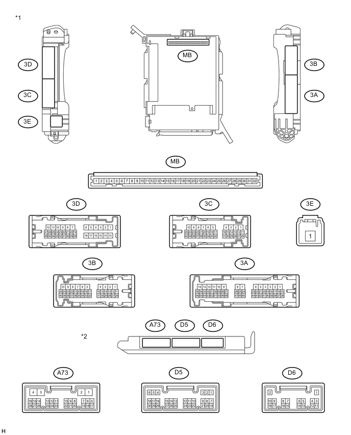
Text in illustration *1 Instrument Panel Junction Block Assembly *2 Main Body ECU (Network Gateway ECU)
-
Remove the main body ECU (network gateway ECU) from the instrument panel junction block assembly.
-
Measure the resistance and voltage according to the value(s) in the table below.
Tester Connection Wiring Color Terminal Description Condition Specified Condition MB-1 (BECU) - Body ground None - Body ground Battery power supply Always 11 to 14 V MB-8 (IG) - Body ground None - Body ground Ignition switch power supply Ignition switch ON 11 to 14 V Ignition switch off Below 1 V MB-9 (ACC) - Body ground None - Body ground ACC power supply Ignition switch ACC 11 to 14 V Ignition switch off Below 1 V MB-11 (GND) - Body ground None - Body ground Ground Always Below 1 Ω MB-32 (+B) - Body ground None - Body ground Battery power supply Always 11 to 14 V
-
If the result is not as specified, there may be a malfunction on the wire harness side.
-
-
Disconnect the D5 main body ECU (network gateway ECU) connectors.
-
Measure the voltage according to the value(s) in the table below.
Terminal No. Wiring Color Terminal Description Condition Specified Condition D5-22 (ACC)* - Body ground W - Body ground ACC power supply Ignition switch ACC 11 to 14 V Ignition switch off Below 1 V
-
*: w/ Entry and Start System
-
-
Reinstall the main body ECU (network gateway ECU).
-
Measure the voltage of the wire harness side connectors.
for LHD Tester Connection Wiring Color Terminal Description Condition Specified Condition 3B-13 (FPCY) - Body ground GR - Body ground Front door courtesy light switch RH input Front door RH open Below 1 V Front door RH closed 11 to 14 V 3A-28 (FDCY) - Body ground V - Body ground Front door courtesy light switch LH input Front door LH open Below 1 V Front door LH closed 11 to 14 V D5-4 - Body ground LG - Body ground LIN communication signal Ignition switch ON Pulse generation for RHD Tester Connection Wiring Color Terminal Description Condition Specified Condition 3B-13 (FPCY) - Body ground GR - Body ground Front door courtesy light switch LH input Front door LH open Below 1 V Front door LH closed 11 to 14 V 3A-28 (FDCY) - Body ground V - Body ground Front door courtesy light switch RH input Front door RH open Below 1 V Front door RH closed 11 to 14 V D5-4 - Body ground LG - Body ground LIN communication signal Ignition switch ON Pulse generation If the result is not as specified, the main body ECU (network gateway ECU) or instrument panel junction block assembly may have a malfunction.
-