WINDOW DEFOGGER SYSTEM TERMINALS OF ECU
-
CHECK MAIN BODY ECU (NETWORK GATEWAY ECU)
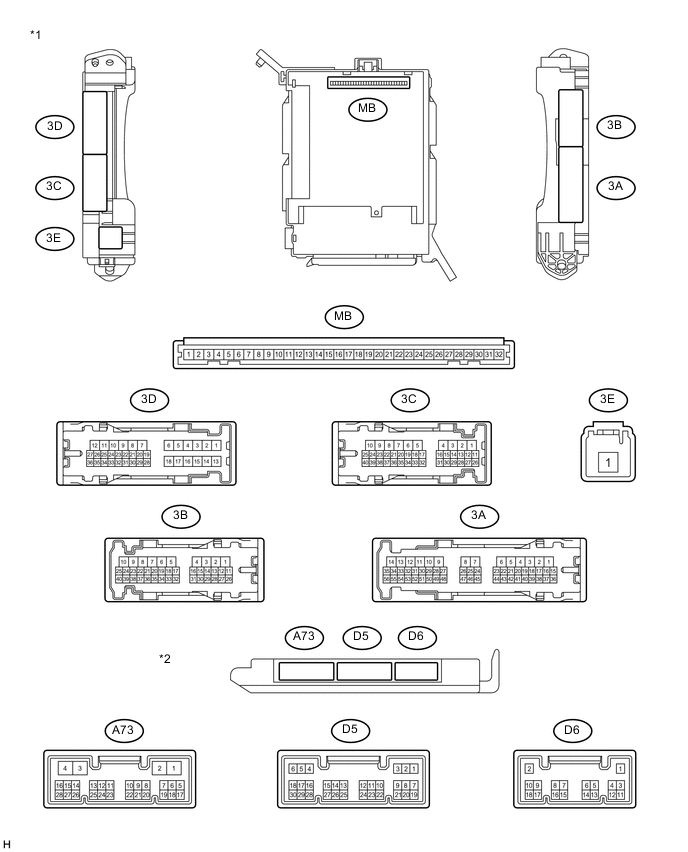
Text in Illustration *1 Instrument Panel Junction Block Assembly *2 Main Body ECU (Network Gateway ECU)
-
Remove the main body ECU (network gateway ECU).
-
Disconnect the A73 main body ECU (network gateway ECU) connector.
-
Measure the voltage and resistance of the wire harness side connector.
Terminal No. (Symbol) Wiring Color Terminal Description Condition Specified Condition A73-24 - Body ground W - Body ground Ignition power supply Ignition switch ON 11 to 14 V Ignition switch off Below 1 V
-
If the result is not as specified, there may be a malfunction on the wire harness side.
-
-
-
CHECK HEATER CONTROL SUB-ASSEMBLY (for Manual Air Conditioning System)
-
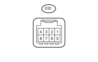
Disconnect the D22 heater control sub-assembly connector.
-
Measure the voltage and resistance of the wire harness side connector.
Terminal No. (Symbol) Wiring Color Terminal Description Condition Specified Condition D22-2 (RDEF+) - D22-4 (RDEF-) W - B-Y Ignition power supply Ignition switch ON 11 to 14 V Ignition switch off Below 1 V D22-4 (RDEF-) - Body ground B-Y - Body ground Ground Always Below 1 Ω
-
If the result is not as specified, there may be a malfunction on the wire harness side.
-
-
Reconnect the D22 heater control sub-assembly connector.
-
Measure the voltage of the connector.
Terminal No. (Symbol) Wiring Color Terminal Description Condition Specified Condition D22-6 (IND+) - D22-4 (RDEF-) R-V - B-Y Rear window defogger signal Ignition switch ON, rear window defogger switch OFF 11 to 14 V Ignition switch ON, rear window defogger switch ON Below 1 V
-
If the result is not as specified, the heater control sub-assembly may have a malfunction.
-
-