UPPER INSTRUMENT PANEL REMOVAL
PROCEDURE
-
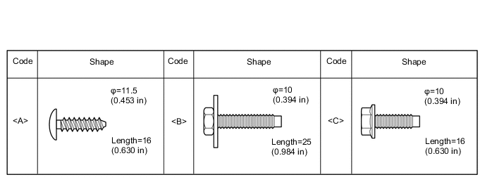
TABLE OF BOLT, SCREW AND NUT
-
All bolts, screws and nuts relevant to installing and removing the instrument panel are shown along with their alphabetical code in the table.
-
-
PRECAUTION
CAUTION:
Be sure to read Precaution thoroughly before servicing Click here.
Note
After turning the ignition switch off, waiting time may be required before disconnecting the cable from the negative (-) battery terminal. Therefore, make sure to read the disconnecting the cable from the negative (-) battery terminal notices before proceeding with work Click here.
-
DISCONNECT CABLE FROM NEGATIVE BATTERY TERMINAL
CAUTION:
Wait at least 90 seconds after disconnecting the cable from the negative (-) battery terminal to disable the SRS system.
Note
-
The power window system utilizes a mechanism that the door glass moves down slightly when the door is opened, and that the glass moves up when closing the door in order to prevent the door molding from being damaged. When the battery negative (-) terminal needs to be disconnected for servicing, fully open the driver and passenger door glasses in advance.
-
-
REMOVE LOWER INSTRUMENT PANEL SUB-ASSEMBLY
-
REMOVE NO. 2 INSTRUMENT PANEL SPEAKER PANEL SUB-ASSEMBLY
-
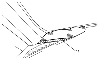
Text in Illustration *1 Protective Tape Apply protective tape to the area shown in the illustration.
-
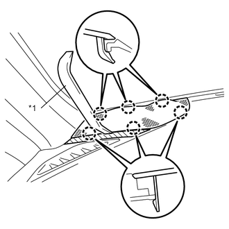
Text in Illustration *1 Moulding Remover Using a moulding remover, disengage the 6 claws and remove the No. 2 instrument panel speaker panel sub-assembly.
-
Disconnect the connector.
-
-
REMOVE FRONT NO. 2 SPEAKER ASSEMBLY (for 6 Speakers)
-
REMOVE NO. 1 INSTRUMENT PANEL SPEAKER PANEL SUB-ASSEMBLY
Tech Tips
Use the same procedure described for the No. 2 instrument panel speaker panel sub-assembly.
-
REMOVE FRONT NO. 2 SPEAKER ASSEMBLY (for 6 Speakers)
-
REMOVE FRONT PILLAR GARNISH LH
-
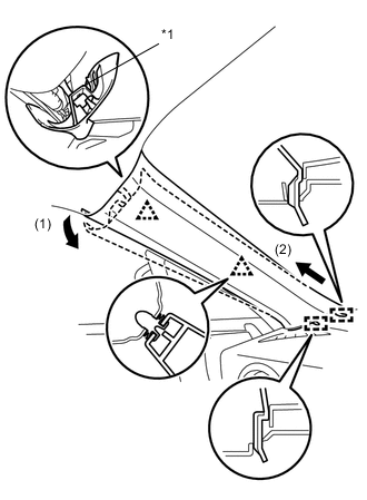
Text in Illustration *1 Front Pillar Garnish Clip Pull the upper part of the front pillar garnish LH in the direction of the arrow (1), and disengage the 2 clips and the front pillar garnish clip.
Tech Tips
The front pillar garnish clip should be remained on the front pillar garnish LH.
-
Pull the front pillar garnish LH in the direction of the arrow (2) and disengage the 2 guides.
-
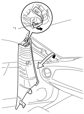
Text in Illustration *1 Front Pillar Garnish Clip Turn the front pillar garnish LH in the direction of the arrow.
Note
While turning, be careful not to damage the curtain shield airbag.
-
Disengage the tip of the front pillar garnish clip and remove the front pillar garnish LH.
Note
-
Do not use any tools to disengage the tip of the front pillar garnish clip.
-
Be careful not to damage the front pillar garnish clip.
-
-
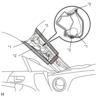
Text in Illustration *1 Curtain Shield Airbag Assembly *2 Adhesive Tape *3 Protective Cover Protect the curtain shield airbag assembly (w/curtain shield airbag).
-
Cover the airbag with a piece of cloth or nylon and secure the edges of the cover with tape as shown in the illustration.
Note
Cover the curtain shield airbag with a protective cover as soon as the front pillar garnish LH is removed.
-
-
REMOVE FRONT PILLAR GARNISH RH
Tech Tips
Use the same procedure described for the LH side.
-
REMOVE COMBINATION METER ASSEMBLY
-
REMOVE INSTRUMENT PANEL ORNAMENT
-
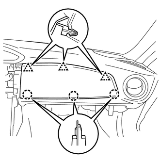
Disengage the 3 clips and 3 claws to remove the instrument panel ornament.
-
-
REMOVE AUTOMATIC LIGHT CONTROL SENSOR (w/ Automatic Light Control System)
-
REMOVE INSTRUMENT PANEL PASSENGER AIRBAG ASSEMBLY
-
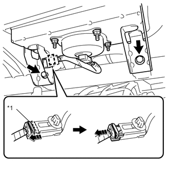
Text in Illustration *1 Slider Disengage the clamp.
-
Slide the slider and disconnect the passenger airbag connector.
-
Remove the 2 bolts and the instrument panel passenger airbag assembly.
-
-
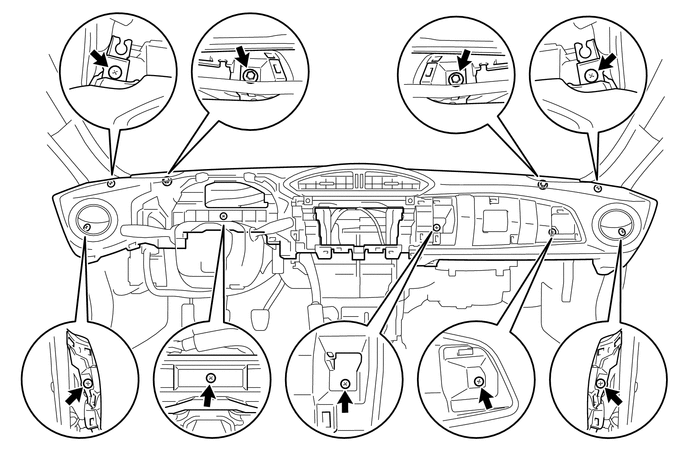
REMOVE INSTRUMENT PANEL SUB-ASSEMBLY
-
Remove the 2 bolts and 7 screws to remove the instrument panel sub-assembly.
-