AIR CONDITIONING PANEL(for Manual Air Conditioning System) INSPECTION
PROCEDURE
-
INSPECT NO. 3 HEATER CONTROL SUB-ASSEMBLY
-
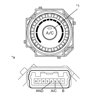
Text in Illustration *1 A/C Switch *a Component without harness connected
(No. 3 heater control sub-assembly)
Check the heater control assembly resistance.
-
Measure the resistance according to the value(s) in the table below.
Standard Resistance Tester Connection Switch Condition Specified Condition 2(B) - 3(A/C) A/C switch OFF 10 kΩ or higher 2(B) - 4(AND) A/C switch OFF 10 kΩ or higher 3(A/C) - 4(AND) Always Below 1 Ω 2(B) - 3(A/C) A/C switch ON Below 1 Ω 2(B) - 4(AND) A/C switch ON Below 1 Ω 5 - 6 Always Below 1 Ω -
Check that the A/C Switch illumination.
OK Measurement Condition Specified Condition Battery positive (+) → 5
Battery negative (-) → 6
illuminates -
Check that the indicator light.
Standard Tester Connection Switch Condition Specified Condition Battery positive (+) → 2
Battery negative (-) → 4
A/C switch OFF go out Battery positive (+) → 2
Battery negative (-) → 4
A/C switch ON come on
-
-
INSPECT HEATER CONTROL SUB-ASSEMBLY
-
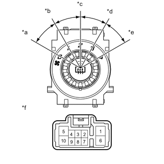
Text in Illustration *a OFF *b LO *c M1 *d M2 *e HI *f Component without harness connected
(heater control sub-assembly)
Check the heater control assembly resistance.
-
Measure the resistance according to the value(s) in the table below.
Standard Resistance Tester Connection Switch Condition Specified Condition each terminal - 5 A/C switch OFF 10 kΩ or higher 10 - 5 A/C switch LO Below 1 Ω 10 - 5 - 3 A/C switch LO - M1 Below 1 Ω 10 - 5 - 3 A/C switch M1 Below 1 Ω 10 - 5 - 3 - 6 A/C switch M1 - M2 Below 1 Ω 10 - 5 - 6 A/C switch M2 Below 1 Ω 10 - 5 - 6 - 1 A/C switch M2 - HI Below 1 Ω 10 - 5 - 1 A/C switch HI Below 1 Ω -
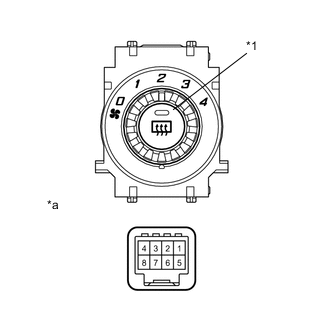
Text in Illustration *1 Rr DEF switch *a Component without harness connected
(heater control sub-assembly)
Check the heater control assembly resistance.
-
Measure the resistance according to the value(s) in the table below.
Standard Resistance Tester Connection Switch Condition Specified Condition 2 - 4 Rr DEF switch OFF 10 kΩ or higher 2 - 4 Rr DEF switch ON Below 1 Ω -
Check that the Rr DEF switch illumination.
OK Measurement Condition Specified Condition Battery positive (+) → 7
Battery negative (-) → 5
illuminates -
Check that the indicator light.
Standard Tester Connection Switch Condition Specified Condition Battery positive (+) → 6
Battery negative (-) → 8
Rr DEF switch OFF go out Battery positive (+) → 6
Battery negative (-) → 8
Rr DEF switch ON come on
-
-
INSPECT NO. 1 HEATER CONTROL SUB-ASSEMBLY
-
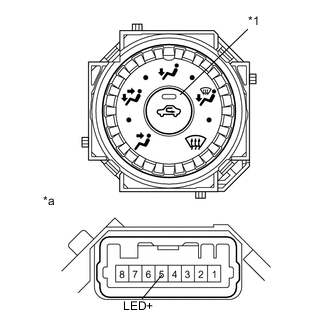
Text in Illustration *1 FRS switch *a Component without harness connected
(No. 1 heater control sub-assembly)
Check that the FRS switch illumination.
OK Measurement Condition Specified Condition Battery positive (+) → 7
Battery negative (-) → 6
illuminates -
Check that the indicator light.
Standard Tester Connection Switch Condition Specified Condition Battery positive (+) → 5(LED+)
Battery negative (-) → 4
FRS switch OFF go out Battery positive (+) → 5(LED+)
Battery negative (-) → 4
FRS switch ON come on
-