AIR CONDITIONING PRESSURE SENSOR ON-VEHICLE INSPECTION
PROCEDURE
-
INSPECT AIR CONDITIONER TUBE AND ACCESSORY ASSEMBLY
-
Check the wire harness.
-
Disconnect the air conditioner tube and accessory assembly connector.
-
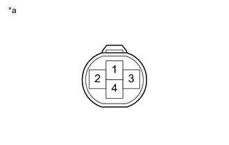
Text in Illustration *a Component without harness connected
(air conditioner tube and accessory assembly)
Using an ohmmeter, measure the resistance of the wire harness side connector.
Standard Resistance Tester Connection Condition Specified Condition 2 - Body ground Always Below 1 Ω 2 - 4 Ignition switch ON Below 1 Ω
-
-
Check the air conditioning pressure sensor.
-
Install a manifold gauge set.
-
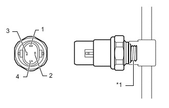
Text in Illustration *1 Sensor Part Apply pressure on the sensor as indicated in the table below, and check the resistance between the terminals.
Standard Resistance for HFC-134a (R134a): Tester Connection Condition Specified Condition 1 - 4 0 kPa (No Pressure applied) 10 kΩ or higher 1 - 4 1520 kPa (15.5 kgf/cm2, 221 psi) Below 1 Ω 2 - 3 0 kPa (No Pressure applied) 10 kΩ or higher 2 - 3 22.5 kPa (0.23 kgf/cm2, 33.0 psi) or more and below 3140 kPa (32 kgf/cm2, 455 psi) Below 1 Ω 2 - 3 3140 kPa (32 kgf/cm2, 455 psi) or more 10 kΩ or higher Standard Resistance for HFO-1234yf (R1234yf): Tester Connection Condition Specified Condition 1 - 4 0 kPa (No Pressure applied) 10 kΩ or higher 1 - 4 1520 kPa (15.5 kgf/cm2, 221 psi) Below 1 Ω 2 - 3 0 kPa (No Pressure applied) 10 kΩ or higher 2 - 3 248 kPa (2.53 kgf/cm2, 36.5 psi) or more and below 2980 kPa (30.4 kgf/cm2, 438 psi) Below 1 Ω 2 - 3 2980 kPa (30.4 kgf/cm2, 438 psi) or more 10 kΩ or higher
-
-