FRONT EVAPORATOR TEMPERATURE SENSOR INSTALLATION
PROCEDURE
-
INSTALL NO. 1 COOLER THERMISTOR
-
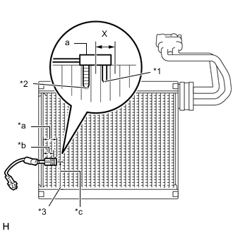
Install the No. 1 cooler thermistor as shown in the illustration.
Part Length *a 34.3 mm *b 27.6 mm *c 50 mm Text in Illustration *1 Sensor Part *2 Fixed Part *3 from Tank Note
-
Be sure to insert the thermistor only once because reinserting it will not allow it to be firmly secured.
-
When reusing the evaporator, insert the thermistor one row next to the one that has been used previously (X in the illustration).
-
After inserting the thermistor, do not apply excessive force to the wire.
-
Directly insert the thermistor until the edge of plastic case "a" comes into contact with evaporator "b".
-
-
-
INSTALL AIR CONDITIONER TUBE ASSEMBLY
-
INSTALL NO. 1 COOLER EVAPORATOR SUB-ASSEMBLY
-
INSTALL COOLING UNIT CASE SUB-ASSEMBLY (for Automatic Air Conditioning System)
-
INSTALL COOLING UNIT CASE SUB-ASSEMBLY (for Manual Air Conditioning System)
-
INSTALL COOLER EXPANSION VALVE
-
INSTALL HEATER CONTROL CABLE SUB-ASSEMBLY (for Manual Air Conditioning System)
-
INSTALL AIR INLET DAMPER CONTROL CABLE SUB-ASSEMBLY (for Manual Air Conditioning System)
-
INSTALL ASPIRATOR PIPE (for Automatic Air Conditioning System)
-
INSTALL ASPIRATOR (for Automatic Air Conditioning System)
-
INSTALL AIR CONDITIONING UNIT ASSEMBLY (for Automatic Air Conditioning System)
-
INSTALL AIR CONDITIONING UNIT ASSEMBLY (for Manual Air Conditioning System)
-
CONNECT CABLE TO NEGATIVE BATTERY TERMINAL
- Torque:
- 6.0 N*m { 61 kgf*cm, 53 in.*lbf }
-
ADD ENGINE COOLANT
-
CHARGE WITH REFRIGERANT
-
for HFC-134a (R134a):
-
for HFO-1234yf (R1234yf):
-
-
INSPECT FOR COOLANT LEAK
-
WARM UP ENGINE
-
for HFC-134a (R134a):
-
for HFO-1234yf (R1234yf):
-
-
INSPECT FOR REFRIGERANT LEAK
-
for HFC-134a (R134a):
-
for HFO-1234yf (R1234yf):
-
-
INSPECT SRS WARNING LIGHT