LOWER INSTRUMENT PANEL REMOVAL
PROCEDURE
-
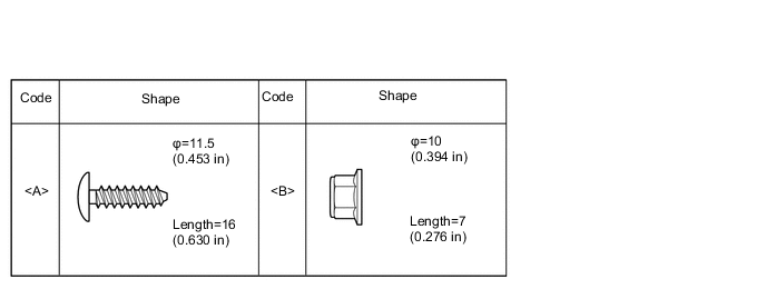
TABLE OF BOLT, SCREW AND NUT
-
All bolts, screws and nuts relevant to installing and removing the instrument panel are shown along with an alphabetical code in the table.
-
-
PRECAUTION
Note
After turning the ignition switch off, waiting time may be required before disconnecting the cable from the negative (-) battery terminal. Therefore, make sure to read the disconnecting the cable from the negative (-) battery terminal notices before proceeding with work Click here.
-
DISCONNECT CABLE FROM NEGATIVE BATTERY TERMINAL
-
REMOVE CONSOLE BOX ASSEMBLY
-
REMOVE INSTRUMENT PANEL ORNAMENT (w/ Large Ornament Panel)
-
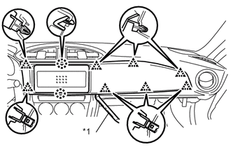
Text in Illustration *1 Moulding Remover Using a moulding remover, disengage the 8 clips and 2 claws to remove the instrument panel ornament.
-
-
REMOVE CENTER INSTRUMENT CLUSTER FINISH PANEL SUB-ASSEMBLY (w/o Large Ornament Panel)
-
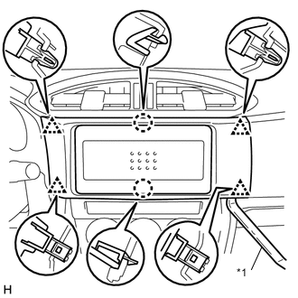
Text in Illustration *1 Moulding Remover Using a moulding remover, disengage the 2 claws and 4 clips to remove the center instrument cluster finish panel sub-assembly.
-
-
REMOVE STEREO OPENING COVER WITH BRACKET (w/o Radio Receiver)
-
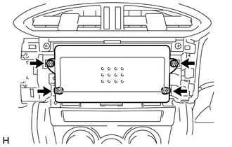
Remove the 4 screws to remove the stereo opening cover with bracket.
-
-
REMOVE RADIO RECEIVER ASSEMBLY WITH BRACKET (w/ Radio Receiver)
-
REMOVE NO. 2 INSTRUMENT CLUSTER FINISH PANEL GARNISH
-
Remove the screw.
-
Disengage the 6 claws to remove the No. 2 instrument cluster finish panel garnish.
-
-
REMOVE UPPER INSTRUMENT PANEL FINISH PANEL SUB-ASSEMBLY (for LH Side)
-
Remove the screw.
-
Disengage the 3 claws to remove the upper instrument panel finish panel sub-assembly.
-
-
REMOVE NO. 1 INSTRUMENT CLUSTER FINISH PANEL GARNISH
Tech Tips
Use the same procedure as for the No. 2 instrument cluster finish panel garnish.
-
REMOVE UPPER INSTRUMENT PANEL FINISH PANEL SUB-ASSEMBLY (for RH Side)
Tech Tips
Use the same procedure as for the LH side.
-
REMOVE AIR CONDITIONING CONTROL ASSEMBLY (for Automatic Air Conditioning System)
-
REMOVE AIR CONDITIONING CONTROL ASSEMBLY (for Manual Air Conditioning System)
-
REMOVE AIR CONDITIONING CONTROL ASSEMBLY (w/o Air Conditioning System)
Tech Tips
Use the same procedure as for the manual air conditioning system.
-
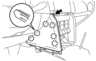
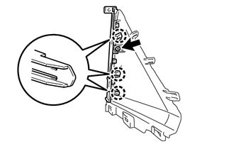
REMOVE INSTRUMENT SIDE PANEL RH (w/ Airbag Cut Off Switch)
-
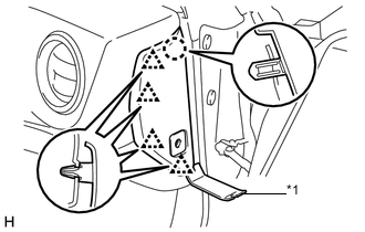
Text in Illustration *1 Moulding Remover Using a moulding remover, disengage the claw and 4 clips.
-
Disconnect the connector and remove the instrument side panel RH.
-
-
REMOVE INSTRUMENT SIDE PANEL RH (w/o Airbag Cut Off Switch)
-
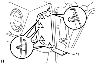
Text in Illustration *1 Moulding Remover Using a moulding remover, disengage the claw and 4 clips and remove the instrument side panel RH.
-
-
REMOVE INSTRUMENT SIDE PANEL LH
Tech Tips
Use the same procedure as for the RH side.
-
REMOVE METER HOOD SUB-ASSEMBLY
-
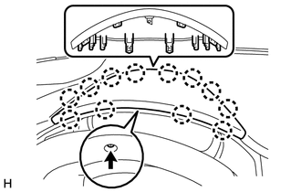
Remove the screw.
-
Disengage the 12 claws, and then pull out the meter hood sub-assembly diagonally upwards to remove it.
-
-
REMOVE UPPER INSTRUMENT PANEL METER ORNAMENT
-
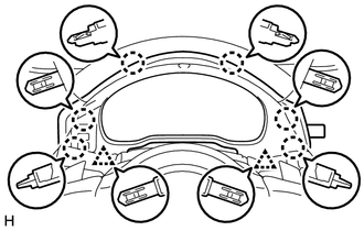
Disengage the 6 claws and 2 clips.
-
Disengage the 2 claws that are holding the upper instrument panel meter ornament and steering column cover together.
-
Disconnect the connector and remove the upper instrument panel meter ornament.
-
-
REMOVE NO. 1 INSTRUMENT PANEL UNDER COVER SUB-ASSEMBLY (w/ Knee Airbag)
-
REMOVE NO. 2 INSTRUMENT PANEL UNDER COVER SUB-ASSEMBLY (w/ Knee Airbag)
-
for LHD
-
Remove the screw.
-
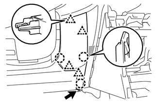
Disengage the 3 claws and 4 clips and remove the No. 2 instrument panel under cover sub-assembly .
-
-
for RHD
-
Remove the screw.
-
Disengage the 3 claws and 4 clips.
-
Disconnect the cooler thermistor hose and connector and remove the No. 2 instrument panel under cover sub-assembly .
-
-
-
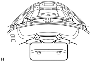
REMOVE GLOVE COMPARTMENT DOOR ASSEMBLY
-
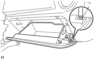
Text in Illustration *1 Glove Compartment Door Damper Disengage the claw and release the glove compartment door damper.
-
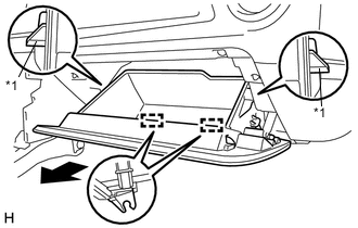
Text in Illustration *1 Stopper Release the 2 stoppers and open the glove compartment door assembly until it is horizontal.
-
Pull the glove compartment door assembly horizontally backward to disengage the 2 hinges and remove the glove compartment door assembly.
Note
Be sure to pull the glove compartment door assembly horizontally to remove it.
-
-
REMOVE GLOVE COMPARTMENT DOOR DAMPER
-
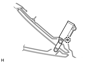
Disengage the claw and remove the glove compartment door damper.
-
-
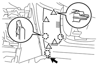
REMOVE LOWER INSTRUMENT PANEL SUB-ASSEMBLY
-
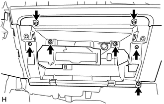
Remove the 7 screws.
-
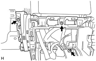
Remove the 2 screws and nut.
-
Disconnect the connectors.
-
Disconnect the aspirator pipe from the air conditioning unit assembly (for LHD with Automatic Air Conditioning System).
-
Disengage the 12 claws and clamp to remove the lower instrument panel sub-assembly.
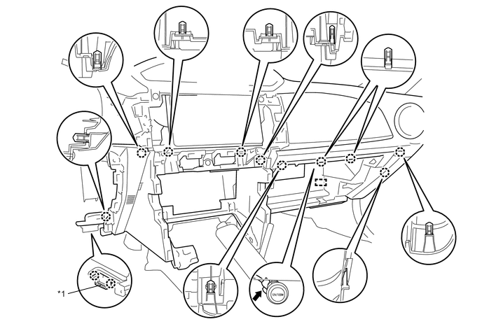
Text in Illustration *1 DLC3 - -
-