AIR CONDITIONING SYSTEM(for Automatic Air Conditioning System) Air Conditioning Compressor Magnetic Clutch Circuit
DESCRIPTION
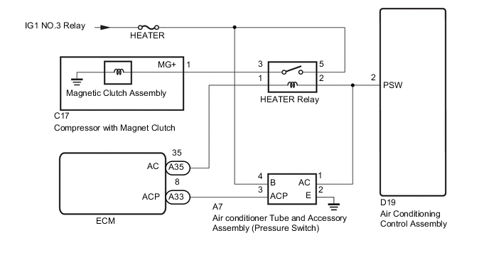
When the air conditioning control assembly is turned on, a magnetic clutch on signal is sent from the heater relay terminal of the air conditioning control assembly. Then, the engine room relay block assembly turns on to operate the magnetic clutch assembly.
WIRING DIAGRAM
CAUTION / NOTICE / HINT
Note
-
Inspect the fuses for circuits related to this system before performing the following inspection procedure.
PROCEDURE
-
READ VALUE USING GTS
-
Enter the following menus : Body Electrical / Air Conditioner / Date List.
-
Check the valve(s) by referring to the table below.
Air Conditioner Tester Display Measurement Item/Range Normal Condition Diagnostic Note Pressure Switch Operation
(Pressure Switch Oper)
Pressure switch status /
Normal or Abnormal
Normal - OK The display is as specified in the normal condition column. Result Proceed to NG A OK B
B 
READ VALUE USING GTS Click here
A 
-
-
CHECK REFRIGERANT VOLUME
-
Check the refrigerant volume (for HFC-1234yf (R1234yf)) Click here
-
Check the refrigerant volume (for HFC-134a (R134a)) Click here
NG 
CHARGE REFRIGERANT
OK
-
-
CHECK HARNESS AND CONNECTOR (AIR CONDITIONER TUBE AND ACCESSORY ASSEMBLY - POWER SOURCE)
-
Disconnect the A7 air conditioner tube and accessory assembly connector.
-
Measure the voltage according to the value(s) in the table below.
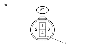
Standard Voltage Tester Connection Condition Specified Condition A7-4(B) - Body ground Ignition switch on 11 to 14 V Text in Illustration *a Front view of wire harness connector
(to Air Conditioner Tube and Accessory Assembly)
NG
REPAIR OR REPLACE HARNESS AND CONNECTOR
OK
-
-
CHECK HARNESS AND CONNECTOR (AIR CONDITIONER TUBE AND ACCESSORY ASSEMBLY - BODY GROUND)
-
Measure the resistance according to the value(s) in the table below.
Standard Resistance Tester Connection Condition Specified Condition A7-2(E) - Body ground Always Below 1 Ω
NG
REPAIR OR REPLACE HARNESS AND CONNECTOR
OK
-
-
CHECK HARNESS AND CONNECTOR (AIR CONDITIONER TUBE AND ACCESSORY ASSEMBLY - ECM)
-
Disconnect the A33 ECM connector.
-
Measure the resistance according to the value(s) in the table below.
Standard Resistance Tester Connection Condition Specified Condition A7-3(ACP) - A33-8(ACP) Always Below 1 Ω A7-3(ACP) - Body ground Always 10 kΩ or higher
NG
REPAIR OR REPLACE HARNESS AND CONNECTOR
OK
-
-
CHECK HARNESS AND CONNECTOR (AIR CONDITIONER TUBE AND ACCESSORY ASSEMBLY - AIR CONDITIONING CONTROL ASSEMBLY)
-
Disconnect the D19 air conditioning control assembly connector.
-
Measure the resistance according to the value(s) in the table below.
Standard Resistance Tester Connection Condition Specified Condition A7-1(AC) - D19-2(PSW) Always Below 1 Ω A7-1(AC) - Body ground Always 10 kΩ or higher
NG
REPAIR OR REPLACE HARNESS AND CONNECTOR
OK
-
-
INSPECT AIR CONDITIONER TUBE AND ACCESSORY ASSEMBLY
-
Inspect the air conditioner tube and accessory assembly Click here
OK
REPLACE ECM
NG
REPLACE AIR CONDITIONER TUBE AND ACCESSORY ASSEMBLY
-
-
READ VALUE USING GTS
-
Connect the GTS to the DLC3.
-
Turn the ignition switch to ON.
-
Turn the GTS on.
-
Enter the following menus : Powertrain / Engine and ECT / Date List.
-
Check the value(s) by referring to the table below.
Engine Tester Display Measurement Item/Range Normal Condition Diagnostic Note A/C Signal A/C switch status / ON or OFF ON: A/C switch on
OFF: A/C switch off
The air conditioning control assembly sends the A/C switch signal to the ECM via CAM communication OK The display is as specified in the normal condition column. Result Proceed to NG A OK B
B
INSPECT RELAY (HEATER) Click here
A
-
-
CHECK HARNESS AND CONNECTOR (HEATER RELAY - AIR CONDITIONING CONTROL ASSEMBLY)
-
Remove the heater relay from the engine room relay block assembly.
-
Disconnect the D19 air conditioning control assembly connector.
-
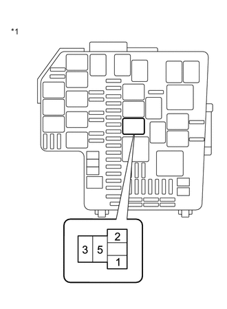
Text in Illustration *1 Engine room relay block assembly Measure the resistance according to the value(s) in the table below.
Standard Resistance Tester Connection Condition Specified Condition 2 - D19-2(PSW) Always Below 1 Ω 2 - Body ground Always 10 kΩ or higher
NG
REPAIR OR REPLACE HARNESS AND CONNECTOR
OK
-
-
CHECK HARNESS AND CONNECTOR (HEATER RELAY - ECM)
-
Disconnect the A35 ECM connector.
-
Text in Illustration *1 Engine room relay block assembly Measure the resistance according to the value(s) in the table below.
Standard Resistance Tester Connection Condition Specified Condition A35-35(AC) - 1 Always Below 1 Ω A35-35(AC) - Body ground Always 10 kΩ or higher
NG
REPAIR OR REPLACE HARNESS AND CONNECTOR
OK
-
-
INSPECT RELAY (HEATER)
-
Inspect the heater relay Click here.
NG
REPLACE HEATER RELAY
OK
-
-
CHECK HARNESS AND CONNECTOR (HEATER RELAY - POWER SOURCE)
-
Text in Illustration *1 Engine room relay block assembly Measure the voltage according to the value(s) in the table below.
Standard Resistance Tester Connection Condition Specified Condition 5 - Body ground Ignition switch off Below 1 V Ignition switch on 11 to 14 V
NG
REPAIR OR REPLACE HARNESS AND CONNECTOR
OK
-
-
CHECK HARNESS AND CONNECTOR (HEATER RELAY - COMPRESSOR WITH MAGNET CLUTCH)
-
Disconnect the C17 compressor with magnet clutch connector.
-
Text in Illustration *1 Engine room relay block assembly Measure the valve(s) in the table below.
Standard Resistance Tester Connection Condition Specified Condition C17-1(MG+) - 3 Always Below 1 Ω C17-1(MG+) - Body ground Always 10 kΩ or higher
NG
REPAIR OR REPLACE HARNESS AND CONNECTOR
OK
-
-
INSPECT COMPRESSOR WITH MAGNET CLUTCH
-
Inspect the compressor with magnet clutch Click here.
NG
REPLACE COMPRESSOR WITH MAGNET CLUTCH Click here
OK
-
-
INSPECT AIR CONDITIONING CONTROL ASSEMBLY
-
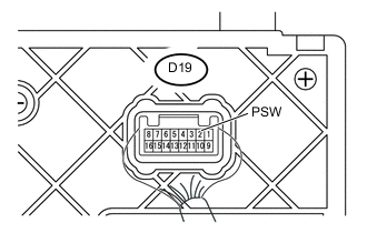
Text in Illustration *1 Component with harness connected
(Air Conditioning Control Assembly)
Measure the voltage according to the valve(s) in the table below.
Standard Voltage Tester Connection Condition Specified Condition D19-2(PSW) - Body ground
-
Ignition switch on
-
A/C switch : off
11 to 14 V
-
Ignition switch on
-
A/C switch : on
Below 1 V -
NG
REPLACE AIR CONDITIONING CONTROL ASSEMBLY Click here
OK
-
-
REPLACE ECM
-
Replace the blower resistor with a new or normally functioning one Click here
NEXT
-
-
READ VALUE USING GTS
-
Enter the following menus : Body Electrical / Air Conditioner / Date List.
-
Check the valve(s) by referring to the table below.
Air Conditioner Tester Display Measurement item/Range Normal Condition Diagnostic Note Pressure Switch Operation
(Pressure Switch Oper)
Pressure switch status /
Normal or Abnormal
Normal -
OK
END (ECM IS FAULTY)
NG
REPLACE AIR CONDITIONING CONTROL ASSEMBLY Click here
-