AIR CONDITIONING SYSTEM(for Automatic Air Conditioning System) Blower Motor Circuit
DESCRIPTION
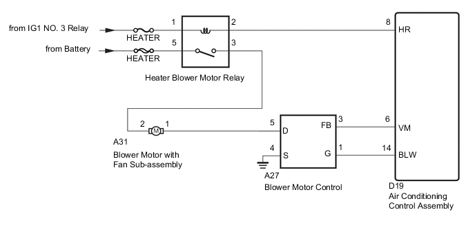
The blower motor with fan sub-assembly is operated by signals from the air conditioning control assembly. Blower motor speed signals are transmitted in accordance with changes in the duty ratio.
WIRING DIAGRAM
CAUTION / NOTICE / HINT
Note
Inspect the fuses for circuits related to this system before performing the following inspection procedure.
PROCEDURE
-
PERFORM ACTIVE TEST USING GTS
-
Connect the GTS to the DLC3.
-
Turn the ignition switch to ON.
-
Turn the GTS on.
-
Enter the following menus: Body Electrical / Air Conditioner / Active Test.
-
Check the operation by referring to the table below.
Air Conditioner Tester Display Test Part Control Range Diagnostic Note Blower Motor Blower motor with fan sub-assembly Min.: 0, Max.: 31 - Result Result Proceed to OK A NG (Blower motor with fan sub-assembly does not operate) B NG (Blower motor with fan sub-assembly operates but does not change speed) C
A 
PROCEED TO NEXT SUSPECTED AREA SHOWN IN PROBLEM SYMPTOMS TABLE
C 
CHECK HARNESS AND CONNECTOR (BLOWER MOTOR FAN SUB-ASSEMBLY-BLOWER RESISTOR) Click here
B 
-
-
INSPECT HEATER BLOWER MOTOR RELAY ASSEMBLY
-
Remove the heater blower motor relay assembly.
-
Inspect the heater blower motor relay assembly Click here.
NG
REPLACE HEATER BLOWER MOTOR RELAY
OK
-
-
CHECK HARNESS AND CONNECTOR (HEATER BLOWER MOTOR RELAY ASSEMBLY - AIR CONDITIONING CONTROL ASSEMBLY)
-
Inspect the heater blower motor relay assembly.
-
Disconnect the D19 air conditioning control assembly.
-
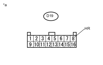
Text in Illustration *a Front view of wire harness connector
(to Air Conditioning Control Assembly)
Measure the voltage according to the value(s) in the table below.
Standard Voltage Tester Connection Condition Specified Condition D19-8(HR) - Body ground Always 11 to 14 V
NG
REPAIR OR REPLACE HARNESS OR CONNECTOR
OK
-
-
CHECK HARNESS AND CONNECTOR (BLOWER MOTOR WITH FAN SUB-ASSEMBLY - POWER SOURCE)
-
Disconnect the A31 blower motor with fan sub-assembly.
-
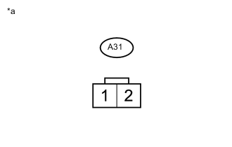
Text in Illustration *a Front view of wire harness connector
(to Blower Motor with Fan Sub-assembly)
Measure the voltage according to the value(s) in the table below.
Standard Voltage Tester Connection Condition Specified Condition A31-2 - Body ground Ignition switch ON
Blower switch ON
11 to 14 V
NG
REPAIR OR REPLACE HARNESS OR CONNECTOR
OK
-
-
INSPECT BLOWER MOTOR WITH FAN SUB-ASSEMBLY
-
Reconnect the blower motor with fan sub-assembly Click here.
-
Inspect the blower motor with fan sub-assembly Click here.
NG
REPLACE BLOWER FAN MOTOR ASSEMBLY
OK
-
-
CHECK HARNESS AND CONNECTOR (BLOWER MOTOR FAN SUB-ASSEMBLY-BLOWER RESISTOR)
-
Disconnect the A27 blower resistor.
-
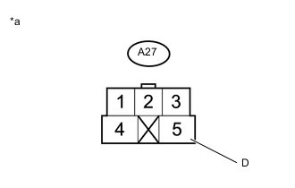
Text in Illustration *a Front view of wire harness connector
(to blower resistor)
Measure the voltage according to the value(s) in the table below.
Standard Voltage Tester Connection Condition Specified Condition A27-5(D) - Body ground Ignition switch ON
Blower switch ON
11 to 14 V
NG
REPAIR OR REPLACE HARNESS OR CONNECTOR
OK
-
-
CHECK HARNESS AND CONNECTOR (BLOWER MOTOR WITH FAN SUB-ASSEMBLY BODY GROUND)
-
Disconnect the A27 air conditioning control assembly connector.
-
Measure the resistance according to the value(s) in the table below.
Standard Resistance Tester Connection Condition Specified Condition A27-4(S) - Body ground Always Below 1 Ω
NG
REPAIR OR REPLACE HARNESS OR CONNECTOR
OK
-
-
CHECK HARNESS AND CONNECTOR (AIR CONDITIONING AMPLIFIER ASSEMBLY - BLOWER MOTOR CONTROL)
-
Disconnect the D19 air conditioning control assembly connector.
-
Measure the resistance according to the value(s) in the table below.
Standard Resistance Tester Connection Condition Specified Condition A27-1(G) - D19-14(BLW) Always Below 1 Ω A27-3(FB) - D19-6(VM) Always Below 1 Ω A27-1(G) - Body ground Always 10 kΩ or higher A27-3(FB) - Body ground Always 10 kΩ or higher
NG
REPAIR OR REPLACE HARNESS OR CONNECTOR
OK
-
-
REPLACE BLOWER MOTOR CONTROL
-
Replace the blower motor control with a new or normally functioning one Click here.
NEXT
-
-
PERFORM ACTIVE TEST USING GTS
-
Connect the GTS to the DLC3.
-
Turn the ignition switch to ON.
-
Turn the GTS on.
-
Enter the following menus: Body Electrical / Air Conditioner / Active Test.
-
Check the operation by referring to the table below.
Air Conditioner Tester Display Test Part Control Range Diagnostic Note Blower Motor Blower motor with fan sub-assembly Min.: 0, Max.: 31 -
OK
END (BLOWER MOTOR CONTROL IS FAULTY)
NG
REPLACE AIR CONDITIONING CONTROL ASSEMBLY Click here
-